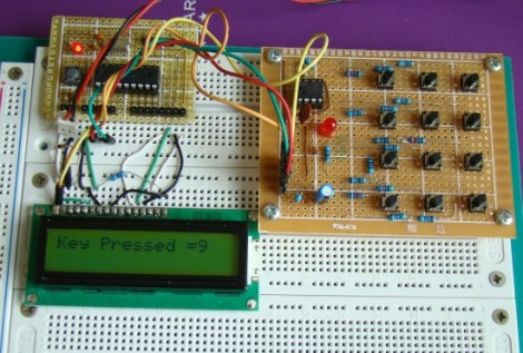
[R-B] designed a 555 timer circuit to scan a keypad. Keypads are common interfaces for small projects and require row and column scanning by a microcontroller. [R-B’s] setup allows you to reduce the number of pins used on the microcontroller to just two. One is an interrupt that is triggered when any of the buttons are pushed, the other reads the frequency from the 555 chip. Each button has its own resistance which alters the frequency of the 555. The microcontroller reads the frequency for 100ms using a timer. The number of timer overflows that occur during that period directly correspond to the button press (five overflows for the numeral 5, zero overflows for the numeral zero).
We usually debounce our button presses for 40 ms, this is more than twice that amount of time but still not a staggering difference. It does make us wonder if you will miss quick button presses? The only really way to know is to try this out yourself. Check out the video after the break and don’t forget to leave a comment with your own experiences in working with the circuit.
[youtube=http://www.youtube.com/watch?v=tQAmQgBgJAE&w=470]


are there * overflows for *?
That is certifiable genius, right there.
Very clever.
Neat!
wouldn’t it be possible to detect simultaneous keypresses. You’d have to generate more timer steps and then map the count to key combinations?
I can’t get my head to work out whether you could come up with a resistor combination that would result in a different value for any key kombination…
A simple ADC circuit would be better than this – but [R-B] uses a PIC16F628A which doesn’t have any ADC channels.
@Marvin
I was thinking this too. It should be possible to use multiple keypresses, as long as every possible combination creates a different resistance value. I think I’ve seen it done in something before (possibly a cheap toy music keyboard?).
@ alan
I know most car’s use the ADC method to detect button presses on their steering wheels.
I am a big fan of the PIC16F628-48 family so great work!
@Marvin
I wonder if a resistance network based on prime numbers might work so every combination generates a unique frequency. But it might be easier to do this for the capacitor instead since capacatances in parallel add.
Carry this too far and drift and error will mess up. The 555 and resistors do not hold frequency good enough for musical pitch accuracy.
Time delays of 40 to 100 ms. are too long for fast human input. The original touch-tone of Bell Labs needed 50 ms. of tone to recognize them. Afraid of fast fingered accountants they handicapped the ten key lay-out into the “bell-bastard” that we use on all TX related devices. Thankfully cash registers and calculators are still standard numeric keypads, bank machines are screwed up.
This is very clever. Well done!
Now, if only we could do this with a full keyboard…
This is almost exactly how hat switches on old gameport joysticks worked. The hat switch buttons were actually connected to a single analog axis input through resistors of different values. On the computer’s side, the game port used a 558 timer (quad 555) to convert the axis rheostat and hat switch impedances to a frequency which could be timed.
@Marvin @Matt
This is simple. Take values so that are one order greater that previous values. 1, 10, 100, 1000 and so on. Of course these do not have to be dectimal values and can be also binary values.
@Marvin @Matt
But you can not have too many buttons that way because resistor values will way too high.
@Kris Lee – Way too high… or way too awesome?
@Pilotgeek
Yes, you are right. I checked available resistors from Mouser and there is resistor with 50 Gigaohm resistance. This is really awesome. Downside is that it does cost 6,68 euro and minimum quantity you can buy is 100.
There is also 10 Gigaohm resistor that does cost 3,42 euro and you can buy just one. I think that when I buy something again from Mouser I will just add one to my order to just check out what my multimeter would think about it.
But it think that it would be possible to build a keyboard with 32 buttons this way. It would be a bit too expensive but completelly doable.
A better solution would be in my opinion many smaller button groups with separate 555 timer. This solution would scale much more easily.
Regarding the multiplexing idea: You probably can’t do more than 6-7 bits this way before the range gets unreasonable. Not the cost or availability of resistors, but the actual ability to discern between the low values while still keeping the high values in range.
Of course, 6 is plenty in most cases and could be easily achieved with common parts.
you’re using 555 IC for what purpose? for debounce? with astable multivibrator or maybe for clock’s source??