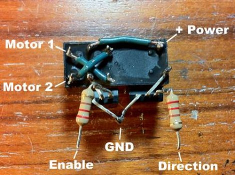
[Nothinglabs] built this motor controller as an alternative to using an H-bridge. They call it the RAT controller which stands for “Relay and Transistors”. You can see above that two Darlington transistors along with their base transistors allow logic signals to switch the relay on and off, driving the motor in one direction or the other based on the open or closed state of the relay. See it working in the video after the break.
It’s a nice little workaround with few parts, but because the relay is mechanical there will be a short lifespan when compared to solid-state motor controllers. That’s okay, because the motivation here was lack of parts on hand, rather than an increase in performance. It’s also worth mentioning that all of these parts can be purchased at your local Radio Shack when you don’t want to wait for component orders by mail. We certainly appreciate that it takes far few components than [David Cook’s] H-bridges. His designs are our favorite – we’ve used them in our own projects – but for quick and dirty you can’t beat five components and the short assembly time needed when using this type of dead-bug style soldering.
[youtube=http://www.youtube.com/watch?v=wvhB0gCcZC0&w=470]


Simple and effective, I like it. One change I’d make is to add a diode reverse-biased across the coil, to keep the transistor from being fried when the coil is switched off.
Good suggestion @Spag. @Nothinglabs, You can also add another “clamping” diode from the TIP120’s Collector (anode here) up to the Power rail (cathode here), to prevent flyback voltage generated by the inductance of the motor windings, from damaging your TIP120. It will help you with regenerative braking as well.
@Brett
Ah yes, forgot about that one.
With these mods, I actually think this circuit will last quite a long time, especially if you make things easier for the relay by turning off power to the motor (via the “enable” line) before switching directions.
This is lame. Perfect for “Instructables”.
Radio Shack … Booo
$9 of stuff bought in Radio Shack = $81 of stuff bought in digikey, mouser, etc.
I’ve built this solution some time ago too. It is efficient as long as you need only seldom actuation of relay or you don’t need much lifespan out of the project.
Nice. More parts-on-hand hacks, HAD!
i got an esc for dc motors that can do a few amps but its for an aircraft and doesn’t have reverse. ive been looking at bridge drivers and mosfets and whatnot to try to retrofit a reverse mode. but then i saw this and immediately knew what to do.
i wouldn’t need the enable pin, since the esc does the pwm already. i figure id use a tiny85 to take the control signal and map it to speed and direction and remake the signal for the esc and also use a pin to control direction. the other pins i can use for alternate interfaces like i2c or fake serial, or for configuration through jumpers.
might also consider a latching servo to reduce the amount of time the coil needs to stay on. also use a coil witch uses less power, so i can drive it with parts i have on hand.
What current is the motor drawing? Is there any chance of the relay contacts welding?
@holly_smoke: Good point, but most of the time this only happens during opening/closing of the relay contacts- a spark gap created where current is travelling causes the weld. As long as the direction is chosen BEFORE the PWM turns on it should be OK, since the TIP120 isn’t going to be able to handle too much current.
make a servo motor with it :)
what about using some of those dual FETs (2* MOSFET in a single 8 pin package)?
you can get them from old laptop motherboards and most of them handle >6A with digital level inputs on the gates.
Thanks for this!!!!! I made this:
http://www.youtube.com/watch?v=VVHzZac-4M4&feature=player_embedded
With your schematic!! Probably gonna follow the suggestion and add a diode, I want it to last…
@Vinh Vu Add two diodes, see above posts ;-)
@Vinh Vu very nice home automation setup. I like the curtains on your projection screen the best. I would suggest a small fire extinguisher by your control box… just in case ;-)