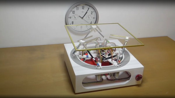
We’ve seen a few H-bridge circuits around these parts before, and here’s another application. This time we have an Old Train Station Clock which has been refurbished after being picked up for cheap at the flea market. These are big analog clocks which used to be common at railway stations around the world.
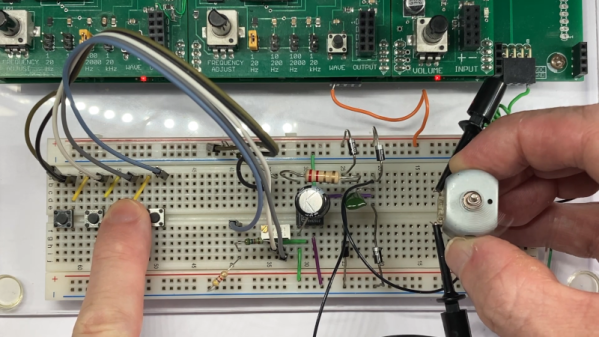
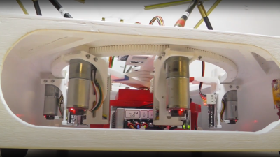
This build uses an ESP32 C3-mini microcontroller (PDF) in combination with an A4988 Microstepping Motor Driver (PDF). The logic is handled with MicroPython code. The A4988 provides two H-bridge circuits, one for each of two stepper motors, only one of which is used in this build.
The controller for this clock needs to send an alternating positive then negative DC pulse every minute to register that a minute has passed so the clock can update its hour hand and minute hand as appropriate. The ESP32 and the A4988 H-bridge cooperate to make that happen. The wifi on the ESP32 C3-mini is put to good use by facilitating the fetching of the current time from the internet. On an hourly basis the clock gets the current time with a HTTP call to a time server API, for whatever is suitable for your time zone.
Thanks to [PiotrTopa] for writing in to let us know about his project. If you’re interested in learning more about H-bridge applications be sure to check out Introduction To The H-bridge Motor Controller and A H-Bridge Motor Controller Tutorial Makes It Simple To Understand.

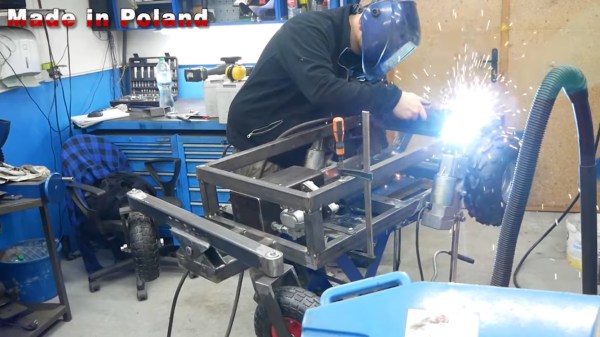
 series of videos from a few years ago, showing the construction and operation of such a beast. This is a very neat mechanism comprised of six geared motors on the end of arms, engaging with a large internal gear. The common end of each arm rides on the central shaft, each with its own bearing. With the addition of the usual six linkages, twelve ball joints, and a few brackets, a complete platform is realised.