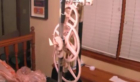
[Stephen Hobley] has been experimenting with an electromagnetic pendulum in order to build himself a clock. Through the course of his experiments, he has learned quite a bit about how pendulums function as well as the best way to keep one moving without the need for chains and weights, which are typically associated with these sorts of clocks.
His first experiments involved driving a simple pendulum with a pulse motor. He discovered that the easiest way to keep the pendulum moving was to use a coil to detect when the it reached the equilibrium point, pushing it along by sending a small pulse to that same coil. He noticed that he could keep the pendulum moving at a pretty good tick if he triggered the magnetic coil every third pass, so he implemented an Arduino to keep count of passes and apply the appropriate force when needed.
He has been making pretty decent headway since his first experiments and now has nearly all of the clock works assembled. Crafted out of wood, he uses a 15-tooth primary drive ratchet, which powers two 60-tooth gears responsible for keeping track of seconds, as well as a pair of larger gears that track the minutes and hours.
It’s looking good so far, we can’t wait to see it when finished.
Stick around to see a quick video demonstration of the clock with all of its gearing in action.
[youtube=http://www.youtube.com/watch?v=ekqBGOcKuJM&w=470]


When in doubt, use an Arduino…
He doesn’t need the Arduino, or the Hall effect sensor either.
The coil he’s using to give the pendulum a kick can also be used as a sensor, electromagnetism goes both ways.
I think one of the more simple ideas to get the coil’s pulse timings would be to put a small neodinium magnet on the arm of the pendulum and mount a reed switch on an adjustable slider. If you wanted to conserve energy you could add two reed switches and a capacitor as a timer so it only triggers when the pendulum has slowed slightly. No more energy hungry microcontroler to eat your batteries (:
Thanks for blogging about the clock!
Just to clarify – there is no Hall effect sensor, just the coil – later upgraded to 2 coils so that the drive coil could be isolated from the sense coil.
The Arduino isn’t required to keep it running, but it is required to log data on the angular velocity of the pendulum, and the period. And to adjust the pulse width and offset of the driving kick – and keep the clock running as accurately as possible.
I wonder if the clock builder understands it’s not the pendulum that drives the gears that move the hands of a clock, buts is a regulating mechanicism. Anyway an interesting way to turn the movement of pendulum into a rotary motion. Personally for time keeping, it may be tough to beat the clock works escapement.
You can see the famous Clayton Boyer’s take on the same subject. It is an interesting design.
http://www.lisaboyer.com/Claytonsite/toucanpage.htm
@D_, in this case the pendulum IS driving the clock – I think I have seen an old IBM master clock that used the same principle. Some clocks use falling weights or springs to power the mechanism, including using a little bit to keep the pendulum going. This one just puts the energy straight in to the pendulum to power everything. This one wseems to be unique in that it only pulses the pendulum when its swing is decaying, and the timing of the pulse is varied to change the period of the pendulum.
Synch this to the PPS output from a GPS receiver for high accuracy.
The pendulum is used to time an escapement. I don’t see what type of escapement is being used.
I’ve always wanted to build a nixie clock with pendulum timebase ;-)