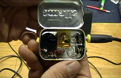
The most recent installment of [Dino Segovis’] Hack a Week covers the construction of a simple NPN transistor audio preamp. Some time ago, he built a small audio amplifier using an LM386 which worked well, but didn’t quite get his music as loud as he would like it. He decided to build a preamp to complement his amplifier, and demonstrates how you too can build one with just a small handful of components.
As the name probably suggests, the cornerstone of this amplifier is an NPN transistor. He explains that a forward bias is applied to the base-emitter junction, which results in the transistor operating halfway between its cut-off and saturation regions. Both halves of the input audio signal are superimposed on this bias voltage, resulting in a decent amount of gain across both channels from a relatively small package.
The preamp isn’t going to win any awards among audiophiles, but it is definitely a great beginner project. Its a novel way of demonstrating how transistors work, while producing a useful takeaway piece of audio equipment at the same time.
Continue reading to see a video showing just how big an effect [Dino’s] NPN preamp had on his music.
[youtube=http://www.youtube.com/watch?v=9SclQIWkOtk&w=470]


I love Dino’s audio projects. Music and art got me tinkering and it’s little doodads like this one that make electronics instantly accessible and rewarding to non-engineer types like me. Very well done sir! Can’t wait for the JFET version. I especially appreciate the abridged theory lesson.
Couldn’t have come at a better time! I have been trying to understand and build my own NPN Transistor Audio Amplifier for a bit now and would like to learn more about the circuitry and how it works.
Unfortunately it’s not viewable in germany due to copyrighted music. I hate it when that happens and I would like to see more hackers thinking about their worldwide audience before posting their videos (or at least to post alternatives without music). This music copyright shit always kind of disrupts the worldwide web video experience for me.
Besides that, I hope Dino has met his standards here, I really enjoyed the other videos he produced fpr the series.
Seconded, video is unavailable in Germany. We should finally get rid of the GEMA. This is ridiculous.
Use hidemyass.com (sometimes needs page reloads to see it) and you can see it.
Regarding the comment that this would not satisfy audiophiles, should that be taken to mean that a simple NPN transistor amplifier like this can’t produce good audio? How good can it be?
This type of audio amplifier lacks strong negative feedback to linearize transfer curve. Low supply voltage makes saturation and cut-off close to active region. With such low supply voltage active region is too narrow to give enough headroom for standard audio signal level.
If the output signal level is several milli-volts to several tens of milli-volts it will work just fine.
I wish Dino spent some time explaining why he used R2 and R3 to bias the Q1 in such way (automatic bias for common emitter configuration)
Supply voltage is 3 to 9 volts and preamp keeps A-class trough the whole supply voltage range.
It would be great lecture to everyone interested in analog electronics.
Potentially very good indeed with a bit of refinement. An LM833 would be getting close to as good as it gets, but then he’s driving an LM386 which is nothing special.
What is R1 there to bias? Should only be required with something like an electret mic.
Good question haha what is R1 doing there? Yeah looks like a mic was originally driving it.
@ColinB. A simple NPN transistor amplifier like this cannot produce good quality audio.
The bias configuration (this one is known as ‘collector feedback’ common emitter amp) is not good enough. One reason is that the AC voltage gain is relying entirely on r’e (which varies with temp etc).
If there had been an analysis and discussion of the design this would have been obvious!
A comment on the site suggests adding a resistor to the emitter, this will give the design much more stability at the cost of gain achieved. But the most of which can be recovered by ‘swamping’ the resistor with a capacitor in parallel whose value must be chosen so it’s reactance won’t interfere too much with the input bandwidth.
Does Dino remind anyone else of Ted Nugent?
God damnit,…
The Video is not available in germany caused by some gema bullshit.
:(
The Class A configuration of an Amp promises the least distortion, at the cost of bias current, which normally would make it unsuitable for battery driven applications. There can be exceptional sounding Amps based on this general Class A design. Have a look here, advanced, but nothing undoable for someone with patience: http://www.mhennessy1.f9.co.uk/mf_a1/technical.htm
Of course Class A amps rock, they also consume vast amounts power and throw out unholy amounts of heat.
What about a simple “Push Pull” amp? Would of been only a couple more components for a lot more gain. I love how I took semiconductors in college but I couldn’t for the life of me conjure up what resistor values to use. Nice, simple current amp though!
sir i made the pre amp for my earphones.but i got stuck because i had to put 3 connections from input i.e. female 3.5mm jack.ground,left and rirht.but i don t know how to do it..pls hlp me out..