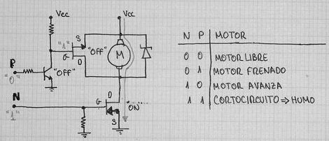
Here’s a nice little circuit that will drive a motor and allow you to stop its rotation, giving your robot a set of brakes. It’s part of [JM’s] post about the in’s and out’s of building microcontroller friendly motor controllers (translated).
This particular setup is a half H-bridge. It allows you to drive the motor in one direction only. The MOSFET used on the ground-side of the motor doesn’t actually need to be there. This is the brake which let you electronically stop the motor from spinning. Without it, the motor will keep turning under its own momentum when the half-bridge is shut off. Depending on the application this can be a big problem. There’s a great demonstration of the circuit braking a fast spinning motor in the video clip below the fold.
It is possible to use this driver with PWM, but [JM] has some warnings about inbuilt functions like FastPWM. Make sure you read his admonition, and if you need a refresher don’t miss this Hackaday video segment.
[youtube=http://www.youtube.com/watch?v=_lqyuR_iWuY&w=470]
[Thanks Javi]


I’d not consider the ground-side mosfet as ‘optional’, since without it the braking mosfet will short Vcc to ground…
It’s not the bottom MOSFET that does the braking, it’s the top one that’s basically shorting the motor. Note that this circuit does not recharge the batteries when braking, all of the energy is dissipated in the motor windings. Also, P-channel devices are hard to find if you require high peak currents and low Rdson, and much more expensive than N-channel devices.
For small to medium sized motors, this is a nice, simple, useful circuit. When driving larger motors, a half bridge with 2 N-channel devices and bootstrap or chargepump circuits are a much batter option. Most hobby robotics projects will probably fall in the “small to medium” range though, so it certainly has it’s place.
Do be careful not to turn on both MOSFETs at the same time, we call this the “fuse test” mode. After turning off one of the MOSFETs, you must wait for a short period (in the low-milliseconds range, depending on the resistors etc.) to prevent shoot-throughs. Also, if the power supply is more than the Vgsmax of the top MOSFET (usually 15-20V), this can not longer work.
What do you mean with “the MOSFET used on the ground-side of the motor doesn’t actually need to be there” ?
Of course it needs to be there, otherwise you’d be shorting out the power supply when trying to brake.
Looks like a nice setup for a forward only ZIPPY line following robot ;-) I like the coroplast frame, cheap and fairly sturdy.
Guessing that “cortocircuto — humo” means “catch fire” or “blow fuse” 8)
It means something like this “if you set N and P at the same time, the result will be a shortcircuit and therefore some magic smoke”
Son of a gun – Humo means smoke. 8)
cortocircuto = short circuit
humo = smoke
It’s funny how both FETs in the schematic diagram are wired incorrectly.
The schematic diagram is correct.
They seem to wired correctly to me. Note that the arrow does not point in the direction of the current, like they do with bipolar transistors. A N-channel MOSFET has the arrow pointing towards the gate, while the arrow points away from the base in the symbol of a NPN transistor. This is somewhat counterintuitive.
The symbols, however, aren’t completely correct; the source should have 2 lines to the gate, and the lines shouldn’t actually touch the gate, but end in lines resembling capacitor plates. Also, I usually draw the body diodes next to the symbol, because they are significant when thinking about the circuit.