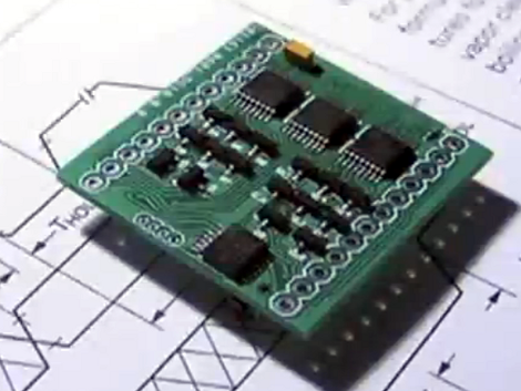
[Greg] is really working on a small scale with his LED Matrix backpack PCB. It’s a toy that he designed as an activity. He constrained himself to a board which would exactly match the outline of an 8×8 bicolor LED matrix package.
What you see here is the side of the PCB which will be facing the underside of the LED dot matrix module. Let’s call this the top of the board. The underside has a CR2032 battery holder which provides enough juice to run the display. Since the matrix is bi-color there’s a slew of pins to drive. [Greg] uses three shift registers for the high side, and sixteen N-channel MOSFETS for the low side. He’s chosen an MSP430G2201 microcontroller which has a nice sleep mode for power conservation. It has no problem driving tri-color animations as seen the clip after the break, but also has an unpopulated clock crystal footprint if you wanted to use it as a timepiece.
Despite the small footprints and cramped board [Greg] still hand soldered all of the components. He even posted a time-lapse of the process in the page linked at the top.
[youtube=http://www.youtube.com/watch?v=sXVhfoKJW7E&w=470]


Nice, I’m working on something similar, though meant to be chained together to make larger displays. Same profile, surface parts and all.
http://www.billporter.info/arduquee-an-arduino-powered-marquee-design-log/
Fun! The only question I have is what is the Vf of the green LED? If it is close to the 3V Vbatt then does the device have trouble keeping the green LEDs lit as the battery voltage droops?
The battery voltage should only drop as the current draw from the battery increases.
This effect is due to the internal resistance of the battery.
The battery voltage also drops as the device is used. You do realize that batteries run down, right? I think that is what he meant.
Of course, if you’re green LED’s stop lighting up, I guess it means it’s time to change your battery. :)
Some additional work with LED display tiles:
http://www.puzzlemation.com/
http://glip.fr/
Reblogged this on Murli's Blog.
Impressive work!