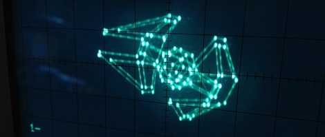
Armed with four wingtip-mounted Sienar Fleet Systems L-s9.3 laser cannons and a SFS P-s5.6 twin ion engine, the TIE Interceptor has become the scourge of the Rebel fleet, nearly capable of out-running and out-maneuvering the beloved A-wings of Nomad Squadron. Because of [Matt]’s tireless work, we can now visualize TIE Interceptors on approach with our targeting computers oscilloscopes.
[Matt]’s oscilloscope visualization of a TIE fighter is a huge improvement on previous scope displays we’ve seen, considering [Matt] used very minimal hardware to display 3D graphics. The build uses an ATMega88 along with a 10-bit DAC to draw lines on the screen. The capacious Mega88 with 8kB of flash and 1kB of SRAM was nearly filled to capacity with [Matt]’s project; to improve the rendering speed of the display, sine & cosine values are pre-computed and stored in flash along with division tables for common values.
The rotation of the TIE fighter is controlled by a serial connection to [Batt]’s desktop. It’s a very impressive piece of work that looks like it would fit into the cinematic aesthetic of The Empire Strikes Back. Check out [Matt]’s video of the TIE rotating in space after the break.
[youtube=http://www.youtube.com/watch?v=S019rSEhRbY&w=470]


the old star wars arcade games used XY displays, that had scope hookups so you could diagnose, fancy scopes with blanking played it picture perfect.
Great write up. However one nitpick, the A-Wings along with the B-Wings surfaced during the interval leading up to the mayhem in the “Return of the Jedi”. In the “Empire Strikes back” it was just X-Wings against those TIE fighters. And sadly the X-Wings and their slightly daft pilots had them surrounded.
Very close to my definition of cool. But why the connecting points are so bright? Bandwidth issues, had to anchor the vectors? No blanking?
Hey snurfel, thanks :) The points are bright due to the EB ‘lingering’ there whilst calculating the next point. There’s a description of the tradeoffs of “calc while you draw” vs “calc first, draw quickly” on my writeup; basically, the scope has no blanking and RAM needs are much reduced doing it this way.
Entire oscilloscope demo. With soundcards left & right channel if i understood correctly.
http://youtu.be/s1eNjUgaB-g
So, at this point are you not turning the oscilloscope into a vector display? (compared to a raster)
It was never anything else. Scopes are already vector displays.
Awesome hack, shame there doesn’t seem to be any schematical detail revealed. I’ve had a festering interest in outputting some custom shapes to my scope for a while now, so I always love to see these.
On that note, hey HAD, d’ye think we could have an article tag/catagorization for these posts using oscilloscopes as output displays? I know I’ve seen more on here in the past, and I’ve little doubt we’ll see more in the future, but connecting any dots between them all takes some pretty active effort.
Great, kid. Don’t get cocky!
Sadly, there is no way for me to mod your comment to the top. Please accept my apologies.
We’re just taking off and spreading our wings. Stay close for the juiciest info on taking your plain jane PC and transforming into a developer or creative hobbyist’s powerhouse!
Are you sure it isn’t [Matt]’s desktop opposed to [Batt]’s desktop?