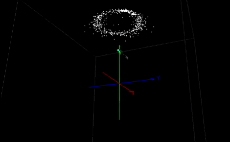
We don’t have much personal experience with DOF hardware, but this Arduino library which reads and compensates for three-axis magnetometer and accelerometer data looks very impressive. It should work for existing hardware, but there’s also a demo design using a Honeywell HMC5883L compass and a Freescale MMA8453Q accelerometer which you can build yourself. Unfortunately these come in QFN packages (like most cheap accelerometers these days) so you may need to be creative when soldering.
What’s so special about this library? Watch the video after the break (use 720p in fullscreen to get the full effect) and you’ll see three different scatter plots of the output data. The image above is a capture of the third example, which is using the hard iron offset and accelerometer compensation. That is to say, metal on and around the board is accounted for, as well as the physical orientation of the device. Even if you have no prior experience with this type of hardware it’s easy to see the usefulness of this kind of software compensation.
[youtube=http://www.youtube.com/watch?v=NF1ezexJuHk&w=470]


A nice write up … but after reading the linked Freescale app note, it doesn’t seem like there was much originality here. Simply ported an excellently written app note from C# to an arduino library (which they did well…. just want to makee sure credit is given where due…)
Didn’t you also see the hard iron solver?
Yes – but I assumed that was taken from AN4246, “Calibrating an eCompass in the Presence of Hard and Soft-Iron Interference” referenced in the app note on page 8.
“DOF Hardware” is non nonsensical. DOF stands for Degrees of Freedom. 6DOF means that the hardware can provide measurements in 6 degrees (x,y,z acceleration and roll, pitch, yaw) The term you’re looking for is Inertial Measurement (although magnetometers aren’t truly inertial measurement devices, they are often included in Inertial Measurement Units for drift compensation)
This is an awesome visualization of magnetometer offset!
That said, all that is needed to calibrate a magnetometer is to find the minimum and maximum readings of each of the three axes. The zero point is (max+min)/2, and the gain can be determined from the value of (max-min).
This is true, however it isn’t so easy to get the max and min directly on axis and in the presence of noise. The auto solver included with the library will pick out the on axis limits with off axis data while rejecting noise.
Michael
Would be a great fit with LSM303, which contains both magnetometer and accelerometer in a single device. It’s LGA14, but it’s not that difficult to solder with a normal iron if you make the pads long enough.
Proof: http://imgur.com/a/0Uwvy#17
I put little beads of solder on the chip pads themselves, tinned the board, and used a hot air gun to melt the solder. I had solder paste, but without a stencil, normal solder is about as easy to use. :|
really nice, I also found an other article claiming auto calibration of HMC5883L http://hobbylogs.me.pn/?p=17, its simple an can be used in a project where very limited sources can be dedicated to the compass. But off course it can not beat the science behind this piece, at least from the looks of it.