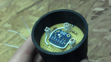
[Richard Osgood] is back again with an interesting project. This time he has constructed a color sensor. His initial design was to use three LEDs and a photoresistor. He would shine a red, then green, then blue LED on a surface and record the reflected light with the photoresistor allowing him to determine how much reflected light there was of each color. Unfortunately, he found it to be completely unreliable. An attempt at using a light frequency sensor didn’t work either. What did finally work, was a luminosity sensor shown above.
Finally, his prototype worked. Unfortunately only the red LED gives readings that he considers to be adequate with the blue and green being “not all quite right”. With this type of circuit, he could build a clone of the magic chameleon lamp.


The premise is flawed because he’s confusing additive with subtractive color.
Real objects don’t have RGB values, they have a spectum of color. Trying to probe the color of a real object with RGB light is like trying to measure the shape of an object by poking it with three thin needles. You get some information, but not enough to say much anything about what the color/shape is unless you move the needles around or change the probing wavelenghts.
But LEDs have relatively wide spectrums, do they not? Lasers would be thin needles, LEDs would be more like wide paddles or something.
They do not.
He needs to have a light source that has a wide continuous emission spectrum instead of a sharp spike.
He can do it if he can get a wideband light source, like a tungsten filament lamp with a known spectral output, and color filters with known filtering responses to get overlapping red, blue and green probes to mimic the function of the eye.
Knowing all their properties, he could then calculate a correction function that translates the spectral properties of the lamp, the filters, and the sensor to match the response of the human eye, and then he could turn it into a corresponding RGB value.
For example, here is a comparison of typical LED spectra with the human eye’s response curve grayed out in the background. The curves are normalized so they’re all the same height.
http://www.jands.com.au/__data/assets/image/0014/27131/luxeon_vs_cones_RGB_LED.png
As you can see, if you used these particular LEDs in your probe, it would be almost impossible to detect yellow and orange hues. They’d get interpreted as some weak shade of green.
Of course, the simplest way to achieve spectral imaging is to use a wide band light source, bounce the light off of the target and split it into its spectrum with a diffraction grating or a small prism. Then use a line sensor to measure the physically separated spectral components.
That way you don’t have to bother with so much math and guesswork. All you need to know is what kind of light you are putting out, and how the line sensor responds to it. Knowing that, you get a fairly accurate spectral graph that you can then compare to the response curve of the eye to see how much RGB it would see.
The surface of a silver pressed CD or a DVD is a good substitute for a diffraction grating.
This may sound negative but why re-invent the wheel when a cheap one already exists? The TCS230 colour to frequency sensor in a SOIC package.
http://www.ebay.com/sch/i.html?_nkw=TCS230%20sensor
Exactly my thoughts. He only needs one of those and a wide spectrum white light as others already posted, not LEDs which have a narrow band of the light spectrum. Impossible to detect reflected light that is not there :P
Well, he could be using many different kinds of LEDs, but then figuring out what the output spectrum is, and then calculating what the sensor output should be is going to be very hairy.
Just getting all the LEDs to shine at pre-determined brightness is going to be a crapshoot as well.
Hey, that TCS230 is a neat chip, but nobody listed in Octopart has any for sale. Is this an EOL chip? Are their any replacements that are more available? Where does one get the TCS230 outside of a pre-packaged module?
Hmm, try looking for the TCS3200 instead, it appears to be the same chip.
It was mostly just to see if I could do it. I had tried and failed a few years ago but I knew i could get it to work if I worked at it a bit more. If I were looking to just use a color sensor for a project then I’d probably use something pre-built. But this project was really to see if I could build one myself. Thanks for the comment.
Redesigning the wheel to make it cheaper/easier to build is quite acceptable IMHO.
I’d have used underdriven GaN LEDs or EL wire as the sensor, as these have predictable outputs at a given current.
:-)
Tricorder build?