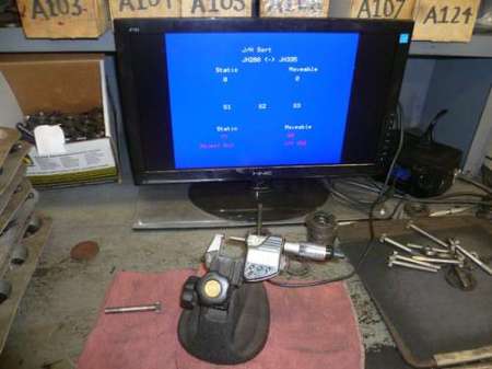
[sspence] found himself in need of a way to push the data from his digital micrometer to a VGA panel for easy display. His micrometer had a data port, so he figured he could plug it into a micro controller and have that push data to a VGA. The micrometer spits out a 52 character data stream in reverse order, so he had to reassemble it in the correct order in software. After a bit of reverse engineering the funky data stream, he had an Arduino pulling the serial data. All that was left was the addition of a VGA shield for output.
He wanted to extend this a bit further though, so he added a foot switch and finger switch to allow for taking multiple measurements and display an average. In the end, he was left with a nice huge display for his micrometer that gave him exactly what he wanted.
We expect that someone will ask why he chose to use an arduino and a shield instead of designing a custom circuit with less components and cost. Our guess would be that his goal was to “generate bin numbers for gear sets” and he just needed an upgraded tool. His goal wasn’t to research design and implement the most efficient circuit. That being said, if anyone feels like designing a smaller package for this, feel free to share with the rest of us!


It’s extremely sad that the HAD editors have to pre-emptivly counter Arduino hating trolls.
My thoughts exactly…
It’s extremely sad that they *tried* to. So now, instead of the *possibility* of that type of discussion, it was expertly called out in the post itself and even has a thread started at the top of the comments (thanks to joe)!
Seriously, I know the target audience here is wide and “if I don’t like it I can leave”, but I keep expecting a little more of an adult ability to run this site and keep being sadly disappointed.
As for the project itself, I personally think there’s nothing wrong with using an arduino to do this. If it gets the job done it’s a great start and good opportunity for someone to pursue an “advanced” project in designing a simplified circuit themselves.
I do think there is something wrong with posting this project and then trying to sell “kits” (which consist mostly of pieces available from many vendors) without making the relationship between the author and the company selling the products (Hacktronics) very obvious.
At least the commercial nature of his subversive advertising is a little more obvious in this “instructable” than some of the others (http://www.instructables.com/id/DIY-Amp-Hour-Meter-Arduino/), where it’s basically a hidden advertisement. That type of advertisement is illegal on blogs (which require full-disclosure), I don’t see why it should be acceptable on “instructables”?
Advertising one’s business on a blog is illegal? I’m sure you’re butthurt about HAD not being up to your surely exacting standards, but why go off the deep end into histrionic lies?
Very cool project. I was just thinking about something like this the other day for engine building. I’d probably use a duino of some sort too… Why not when they’re so easy to acquire and the libraries are there for the using.
Yuck, Deliberate vendor incompatibility.
Starett’s SPC protocol is easier to deal with, pretty much standard ASCII at 1200 baud, with Mitutoyo you have to worry about the clock.
http://www.matronics.com/cncscale/DiagramRev2.pdf
“Mitutoyo SPC data stream consists of 13, 4-bit digits.
Digits are sent LSB (2^0) to the MSB (2^3).
d1 – d2 – d3 – d4 – d5 – d6 – d7 – d8 – d9 – d10 – d11 – d12 – d13
Where:
d1= 0xf (4 nybbles of preamble)
d2= 0xf
d3= 0xf
d4= 0xf
d5= Sign +:0:0000 / -:8:0001
d6 – d11= Digits
d12= Decimal Point Location 0x2:xxxx.xx, etc.
d13= Unit mm:0:0000 / inch:1:1000
Starrett SPC data stream consists of 25 ASCII characters. Characters are sent at
1200 baud, 8 bits (8bit must be masked as it’s state is undefined), no parity, and
2 stop bits. The 25 character stream has the following format:
1-13 = ASCII Spaces (0x20)
14 = Space (0x20) if reading is positive, Minus Sign (-) (0x2d) if reading is negative.
15-21 = ASCII digits representing current reading including a floating decimal point (.) (0x2e).
22 = Space (0x20).
23-24 = Current unit in ASCII. Inches = “in”, Millimeters = “mm”
25 = Carriage Return (0x0d)”
Glad I didn’t have to deal with SPC very often. Metrology is fascinating to me, SPC however is not.
Micrometers like used in Statistical Process Control don’t have a very good “Feel”, it’s the spring loaded anvil. What they are good at are letting anyone on any shift record reasonable and consistent numbers. Really good ones will have a indicator on the anvil side to ensure consistent pressure, tighten until that needle is on the mark. My analog solid anvil mic is more accurate, but I couldn’t hand it so someone else who might not tighten it up the same and expect any accuracy, not even another diemaker.
I have no dog in this “fight”, but, would not a $25 QuickStart Propeller board w/ 3 resistors and an RCA jack be less expensive and smaller than an arduino + VGA shield?
^ ++
I understand the quickest path is what you are familiar with and have on hand, but I have found the Propeller the ‘go-to’ platform for most simple video based projects. I’m an AVR guy at heart, but there’s no denying the ease/cost/performance advantages of the Prop in this area.
Hey, I have a Duinomite for exactly jobs like this one. It can output VGA and is very quickly (re-)programmed thanks to the built-in (!) BASIC interpreter. Cool stuff!