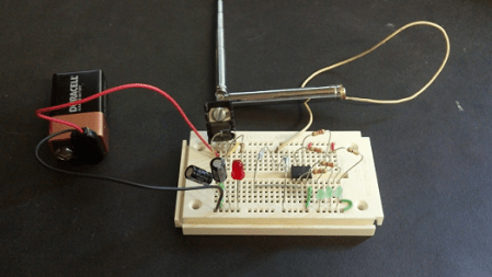
[Scott] wrote in to us with his simple, but well done RF signal strength meter. As he points out in his post, sometimes an Arduino is overkill, so a Picaxe 08M was used instead. Apparently this was a refresh of a high school project that he did. Certainly many of us would have liked to go to that high school!
An interesting part of this project is how he used a laser cutter to produce his PCB traces. This was done by applying black paint to the copper on his board and cutting everywhere he didn’t want copper traces. The results were quite good, and should work well when this project is finalized in an enclosure
Check out the video after the break to see this circuit in action. He explains the build in it, but if you just want to see the signal strength lights come on, fast forward to around 2:25.
[youtube http://www.youtube.com/watch?v=xxyGhsdG6bk&w=470&h=315%5D


There is a mistake in the first schematic, +5V should be taken before the 200R !
The 220R is only there to protect the LED “On” indicator, nothing special…
he stole my idea, i was going to make a lazer-cut board first!
http://i82.servimg.com/u/f82/11/22/64/62/circui21.gif
A whole lot simpler and gives better information.
Your “simpler” version seems to be missing an Arduino. ;-)
That “old school” analog meter in the “whole lot simpler” version certainly costs as much as a box full of microcomputer chips these days, so the digital display is more cost effective (if you eliminate the prototyping board).
+1, work without power supply and cheaper than a “bazooka for fly”. Analog display can be found in garbage in lot of hifi devices…
FartFace, what type of 18 micro fared cap did you use in the RF Signal dectector
What are the specs for the 18 micro fared caps and the 47 K pot, I would like to try this circuit. Could my DVOM suffice for the 0-100 micro Amp meter?
“sometimes an Arduino is overkill, so a Picaxe 08M was used instead”
Umm…. Ok. I really don’t mean to belittle the project, it works! But… If we are going to talk about an Arduino being overkill.. I built one of these with a single MPF102 FET, a mechanical meter and a few passive components when I was in the 5th or 6th grade. I mounted it all in a baby food bottle. I remember running around the house and finding all the power wires in the wall, rf noisy appliances, etc… It worked well to find static charges too.
Again, this project is great. Having a microcontroler even opens it up to perhaps doing some data logging. I just had to comment on the microcontroler being used AND avoiding overkill.. LOL
Assuming one prefers a digital readout to a needle-type analogue meter, a stock digital panel meter will also get the project running faster. I bought one of these tiny DPMs for ~USD5, http://www.all-sun.com/EN/d.aspx?pht=979
However, an needle-type analogue meter is invaluable if the field strength meter is used for aligning (“peaking”) slug-tuned inductors or aerials.
The sensitivity can be improved by adding a capacitor between C2’s cathode and earth. This changes the circuit from average to peak detecting. This kind of voltage doubling detector is used to generate DC from RF in battery-less RFID tags. A good tutorial is AN 1088: Designing the Virtual Battery
http://www.avagotech.com/docs/5966-0785E
can you please upload the code
I hate to say this, but not really that simple. However I can’t judge how simple it is if someone want’s to used LED as indicators
Hey all. im having some issues understanding the schematic. I checked the source and basically tried to copy the schematic from there. just want to make sure i got right http://prntscr.com/9y8crd thats the print screen (will be happy to share the schmatic and PCB layout to anyone who wants it). however im also looking to hook up an arduino to this (to run a few other things too).
How does a human being get electronic signals neutralized, negated, ?
This is a fine example of overkill. An Arduino? Really… I don’t think I’ve seen an Arduino wasted like this. The analog circuit (offered in the comments) will be a more useful tool. In fact I have one here on the bench that I built in Cub Scouts (1970)… still use it regularly.
For the picaxe 08m was there a logic gate programming for the RF signal meter to work? I am unfamiliar with picaxe and was curious if you have to program the chip for the circuit to work or not. If so what gates would you use?
The primary principle right behind these boosters is to augment the surface and then for obtaining and sending communications almost similar to that of a satellite meal antennae. These are lightweight and thin and hence they can snug into any cellphone sans adding any weight or bulk. signalbooster.com