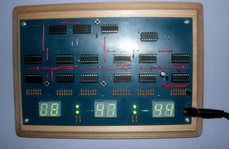
Here’s an IC logic project that displays 24-hour time. Planning was the name of the game for this project. [Mattosx] took the time to layout his design as a PCB in order to avoid the wiring nightmare when build with point-to-point connections.
Much of the complexity is caused by the display itself. Each of the six digits has its own binary-coded decimal chip and array of discrete resistors. Timekeeping is handled by six decade counters, two divider chips, one AND gate chip, and one OR gate chip. He chose a SOIC crystal oscillator chip as the clock signal. We’re more partial to the idea of using mains voltage as the clock signal.
[Mattosx] posted the board artwork if you’d like to etch your own 5″x8″ PCB. Just make sure you read through all of his notes as not all of the chips are oriented in the same direction.
[via Reddit]


Awesome build and ruined it with using the line frequency as clock source. Too bad, that is only long term stable. Short term is very inaccurate.
They should just do it the classical way: use a 32 kHz clock quartz and divide the frequency down into 1 Hz intervals. That’s what these suckers are made for! Classic for discrete logic.
Didn’t read the project website, did you?
“A 32,768 Hz oscillator provides the clock pulse and this is divided by two CMOS 4020 Divider chips down to 1 Hz.”
Did you RTFA?
He uses a 32kHz crystal as the clock source.
It’s the Hack-a-day editors that mentioned using the mains line source.
Indeed.
“He chose a SOIC crystal oscillator chip as the clock signal. We’re more partial to the idea of using mains voltage as the clock signal.”
Bad HAD editors :P Partial to mains as clock signal?
Over long periods mains frequency and therefore time derived is very accurate.
“Over the course of a day, the average frequency is maintained at the nominal value within a few hundred parts per million.” – Standard Handbook for Electrical Engineers
A engineer at a power plant at a dam told me this years ago. They automatically correct the frequency over time.
Now this is cool. We really take for granted the power of microcontrollers. Projects like this make you appreciate how far we’ve come.
Well… you could always put the whole thing in a CPLD or FPGA if you prefer :D
The board actually does use a 32 KHz oscillator and it’s divided down until 1 Hz. It has proved very accurate short term thus far.
Matt
Hey Matt:
Have most of the components and am excited to build this, but it has been a while since I have put together an electronics project from scratch, and so I am looking for a bit more detail on the build. Can I get in touch with you via email?
Hey Mike,
I would love to lend a hand. Email me at mattosx@me.com
Matt
where is all the wiring mess? lol
sweet board layout!
it looks professional.
i’d break the professional look by adding circuitry-lighting ;) XD
(to show the circuits in the dark)
PS: standalone clocks, never did need, and never will need accuracy… 10:37 or 10:38… does it matter?
anyone with enough free time to build such a clock most certainly has enough time so reset the clock once a month or so :)
Uhh why not use an arduino with a real crystal or better still a RTC (maybe Maxim?) combined with a 7 segment display module (Sparkfun has I2C units for cheap)? A bit of code and presto – done.
Because there’s no real challenge in that. I’m sure you’ve heard of that, it’s where you push your own personal limits beyond what you’re initially capable of. Or as the dictionary defines it: difficulty in a job or undertaking that is stimulating to one engaged in it.
Just for suggesting such a silly thing, you should remove “hacker” from your name there.
yeh, should change it to “Builderspacer” lol
Or “duinospacer” :P
Great learning project, I would have used line frequency. I love to see 24 hundred, not that Roman math mess.
Photo fail. Please learn not to blind what you want to show. Take photos with steady balanced light. Take a few, have light on the subjuct change.
Very nice idea and work! Can’t wait to build this or use it as an excuse to learn Eagle! I want to modify it to support 1.5″ 7-segment displays. I’d also like to figure out a way to make it more educational by adding the block diagram to the front of the board. Perhaps printing out and attaching the block diagram to the board under the components or (better yet)figuring out a way to silk screen boards! Every high school robotics club should have one on their wall to demonstrate how far we have gone in a relatively short period of time!