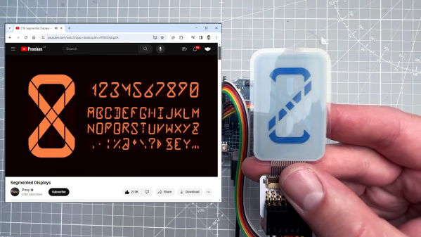
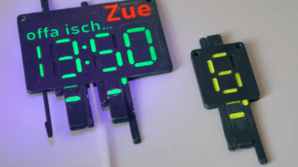
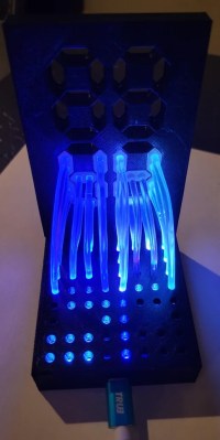
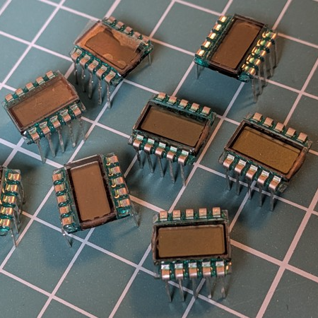
If you’re not aware, there is such a thing as adorable little three digit LCD 7-segment displays. They come in a ten-pin DIP package and are just begging to be integrated into a project. The catch is they are just a tiny bit weird. Luckily for us all, [Nagy Krisztián] spells out exactly how to use them.
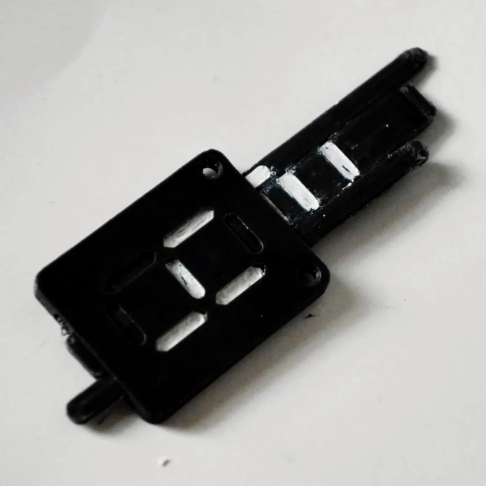
The first odd thing about these ten-pin LCD displays is that they have a footprint that doesn’t quite mesh with standard 0.1 inch spacing, meaning they will not cleanly fit into a breadboard. Luckily, one can solve this with a bit of force. It’s a small part, and the pins don’t seem to mind.
The second odd thing is wrapping one’s head around the pin mapping. Figuring out the table of which pins activate which segments in the digits is easier if one keeps in mind that each segment of each digit is the product of two different pins. For example, “2A” is digit two, segment A, and is the product of pins 3 and COM4.
That’s not all. Electrically speaking, driving this LCD isn’t nearly as straightforward as an LED.
With an LED display, the COM pins are either common anode or common cathode, which tells one whether lighting up a segment means holding the COM pin at GND with voltage applied to the segment pin, or the other way around. But in the case of this LCD display, the polarity applied is swapped every cycle. Oh, and inactive COM pins need to held at half-voltage. Neat!
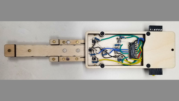
[Nagy] drives the whole thing with little more than an ATtiny84 microcontroller and a few resistors. A switchable half-voltage signal is cleverly created by combining a simple voltage divider and taking advantage of the fact that the ATtiny84’s pins can be in one of three different states depending on how they are configured: high, low, or high-impedance (pin configured as an input). Each COM pin on the display gets connected to both an ATtiny84 pin, and to the supply voltage via two resistors forming a voltage divider. When the ATtiny drives the pin high, the LCD pin sees about 3 V. When the pin is driven LOW, the LCD pin sees 0 V. When the ATtiny configures the pin as an input, the LCD pin receives about 1.5 V.
The bulk of the software is defining which pins and states equal which digits, and cycling the LCD at a rate of vaguely 60 Hz which delivers flicker-free results.
We appreciate the clever combination of voltage divider with pin configuration to create three switchable voltage levels. If you liked that and want to see more serious leveraging of pin configuration on a microcontroller, check out how to drive seven LEDs with only two pins.