Op-Amp Challenge: A Logic-Free BCD

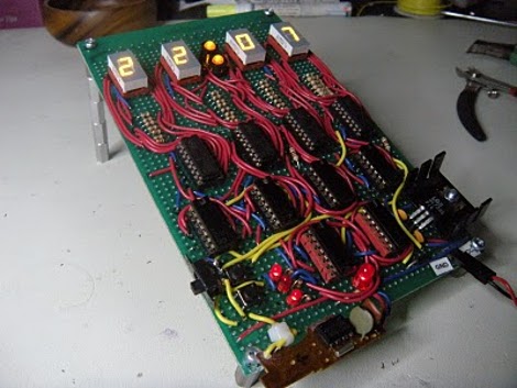
Of digital electronics, a wise man once said that “Every idiot can count to one.” Truer words have rarely been spoken, because at the end of the day, every digital circuit is really just an analog circuit with the interesting bits abstracted away. And to celebrate that way of looking at things, we’re pleased to present this BCD to seven-segment converter that uses no logic chips.

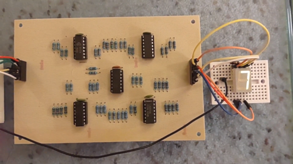
With cheap and easily available chips that perform this exact job, it might seem a little loopy to throw 20 LM324 op-amps at the job. But as [gschmidt958] explains, this is strictly for the challenge, plus it made a nice entry in the recently concluded Op-Amp Challenge contest. His work began in simulation, exploring op-amp versions of the basic logic gates — NAND, AND, OR, and NOT — all of which rely on using the LM324s as comparators. There were real-world curveballs, of course, not least of which was running out of the 10k resistors used for input averaging. Another plot twist was running out of time to order a PCB, which required designing one using MS Paint and etching it at home.

The demo video below shows the circuit at work, taking the BCD output of a 74HC393 counter — clocked by a 555, naturally — and driving a seven-segment LED.  It’s honestly a lot of work for such a simple task, but there’s something satisfying about the whole project. We think [Widlar] would be proud.

Continue reading “Op-Amp Challenge: A Logic-Free BCD”

BCD To I2C: Turning A Nixie Counter Into Whatever You Want It To Be

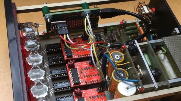
Whenever a project calls for displaying numbers, a 7-segment display is the classic and straightforward choice. However, if you’re more into a rustic, retro, almost mystical, and steampunky look and feel, it’s hard to beat the warm, orange glow of a Nixie tube. Once doomed as obsolete technology of yesteryear, they have since reclaimed their significance in the hobbyist space, and have become such a frequent and deliberate design choice, that it’s easy to forget that older devices actually used them out of necessity for lack of alternatives. Exhibit A: the impulse counter [soldeerridder] found in the attic that he turned into a general-purpose, I2C controlled display.

Instead of just salvaging the Nixie tubes, [soldeerridder] kept and re-used the original device, with the goal to embed an Intel Edison module and connect it via I2C. Naturally, as the counter is a standalone device containing mainly just a handful of SN74141 drivers and SN7490 BCD counters, there was no I2C connectivity available out of the box. At the same time, the Edison would anyway replace the 7490s functionality, so the solution is simple yet genius: remove the BCD counter ICs and design a custom PCB containing a PCF8574 GPIO expander as drop-in replacement for them, hence allowing to send arbitrary values to the driver ICs via I2C, while keeping everything else in its original shape.

Containing six Nixie tubes, the obvious choice is of course to use it as a clock, but [soldeerridder] wanted more than that. Okay, it does display the time, along with the date, but also some sensor values and even the likes on his project blog. If you want to experiment with Nixie tubes yourself, but lack a matching device, Arduino has you obviously covered. Although, you might as well go the other direction then.

Continue reading “BCD To I2C: Turning A Nixie Counter Into Whatever You Want It To Be”

Packing Decimal Numbers Easily

While desktop computers have tons of computing power and storage, some small CPUs don’t have a lot of space to store things. What’s more is some CPUs don’t do multiplication and division very well. Same can be said for FPGAs. So suppose we are going to grab a bunch of three-digit decimal numbers from, say, a serial port. We want to store as many as we can, and we don’t want to do a lot of math because we can’t, it is slow, or perhaps it keeps our processor awake longer and we want to sleep to conserve power. We want a way to pack the numbers as close to the theoretical maximum as we can but with little or no math.

The simple approach is to store the numbers as ASCII. Great for processing since they are probably in ASCII already. If they aren’t, you just add 30 hex to each digit and you are done. That’s awful for storage space, though, since we can store 999 in 10 bits if it were binary and now we are using 24 bits! Storing in binary isn’t a good option, if you play by our rules, by the way. You need to multiply by 10 and 100 (or 10 twice) to get the encoding. Granted, you can change that to two shifts and an add (8x+2x=10x) but there’s no easy way to do the division you’ll have to do for the decode.

Of course, there’s no reason we can’t just store decimal digits. That’s call binary coded decimal or BCD and that has some advantages, too. It is pretty easy to do math on BCD numbers and you don’t get rounding problems. Some CPUs even have specific instructions for BCD manipulation. However, three digits will require 12 bits. That’s better than 24, we agree. But it isn’t as good as that theoretical maximum. After all, if you think about it, you could store 16 distinct codes in 4 bits, and we are storing only 10, so that 6 positions lost. Multiply that by 3 and you are wasting 18 codes.

But there is a way to hit that ten-bit target without doing any math. Its called DPD or densely packed decimal. You can convert three decimal digits into ten bits and then back again with no real math at all. You could implement it with a small lookup table or just do some very simple multiplexer-style logic which means it is cheap and easy to implement in software or onboard an FPGA.

Continue reading “Packing Decimal Numbers Easily”

Learning And Failing At Digital Electronics

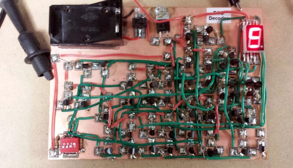
[spencerhamblin] is starting his explorations into digital electronics the hard way: reproducing a “simple” IC’s functionality by wiring up a board full of discrete transistors. In this case, the end product is a binary-to-seven-segment decoder built from scratch.

In engineering circles, this circuit is better known as a 7447 BCD to seven-segment decoder/driver, but just using a single chip has little pedagogical value. Building a simple circuit with 39 transistors, 31 resistors, and a handful of diodes is a good introduction to digital electronics, and after two attempts, [spencerhamblin] knocked it out of the park.

The build began with a piece of copper clad board, a bunch of cheap FETs from fleabay, and an incorrect schematic. While the first version of the project looked fantastic with Manhattan-style construction, and jumper wires everywhere, the schematic was fundamentally flawed and [spencer] got a little confused when converting the circuit to a common anode display.

Version two used a more standardized construction. This circuit was plotted in DipTrace, and the resulting PCB was sent off to OSHPark. The build was cleaner, but in capturing the schematic, [spencer] reversed the footprint of the seven segment display. That was easy enough to fix with a few short wires, and after a little bit of work [spencer] had a device that would convert binary to a seven segment display.

CMOS Logic Clock Tracks 24-hour Time

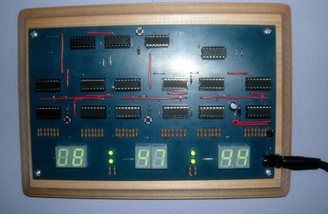
Here’s an IC logic project that displays 24-hour time. Planning was the name of the game for this project. [Mattosx] took the time to layout his design as a PCB in order to avoid the wiring nightmare when build with point-to-point connections.

Much of the complexity is caused by the display itself. Each of the six digits has its own binary-coded decimal chip and array of discrete resistors. Timekeeping is handled by six decade counters, two divider chips, one AND gate chip, and one OR gate chip. He chose a SOIC crystal oscillator chip as the clock signal. We’re more partial to the idea of using mains voltage as the clock signal.

[Mattosx] posted the board artwork if you’d like to etch your own 5″x8″ PCB. Just make sure you read through all of his notes as not all of the chips are oriented in the same direction.

[via Reddit]

Resistor Substitution Box

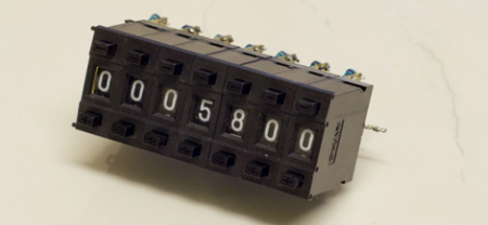
[Vincent] on the EEVblog forums had an idea for an inexpensive resistor substitution decade box.

The build uses cheap decimal thumbwheel switches he bought on eBay. Each switch is wired up with resistors for each digit, and each switch is wired up in series. The result is a small, easy to read resistor box with a range of 1 Ω to 10 MΩ.

Continue reading “Resistor Substitution Box”

Clock Sans-microcontroller

This clock requires no microcontroller. It’s actually a digital logic counter that functions as a timepiece. [BlackCow] used six decade counters to track seconds, minutes, and hours. The output is displayed on four 7-segment digits using BCD-7-segment decoders that you can learn about in our binary encoded decimal post. The actual timekeeping is done by a quartz clock circuit he pulled from a Mickey Mouse clock. This would be a perfect circuit to build in a digital logic simulator, just follow the schematic and learn as you go.