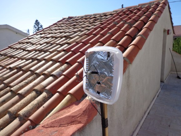
[Danilo Larizza] is sharing a network connection between a couple of apartments. They are not far apart, but they are also not right next to each other so a set of external antennas is necessary. He built this 2.4 GHz biquad antenna on the cheap (translated) just to test if it improved the signal before he tried to buy a proper antenna. It turns out to work well enough that this is all that he needs.
The antenna itself is about one meter of thick wire bent into two squares which are 31mm on each side. The coaxial cable going to the router connects to the center portion of this antenna. For a bit better directional reception he added some tin foil as a reflector. Since this is outdoors he used a food storage container for protection (the antenna is mounted to the lid, the body has been removed for this picture). The whole things is perched on a stake in a flower pot with proper line of sight to the other antenna.
We’ve seen a very similar design used for an NRF 24L01+ radio. If you need more details that [Danilo] posted that would be a good project to study.


SWR is sooo 1990’s
Even Danilo knows that it is aluminum, not tin,
It is often called ‘tin foil’ especially by those that can’t spell aluminum.
It is an odd word. Many others would argue it should be Aluminium, rather than Aluminum. But hey, I could tell what was meant, and spelling isn’t my strong point, so whatever floats your boat.
Most scientific names are those given by the original discoverer and follow that priority. It’s only IUPAC that decided much later that it should be -ium instead of -um so that it would ‘fit’ in with other metals like sodium, potassium &c. Davy the discoverer(A Brit btw) spelled it -um so that’s how it ‘should’ be spelled.
Picking on UIPAC again for another example – should sulfur really be spelt sulphur – as that was the original version of the word? Language is dynamic rather than static, otherwise English as we know it wouldn’t exist.
Aluminium is also Spanish for Aluminum…
I’m old enough to remember real tin foil, before aluminum came to replace it. Waxed paper, tin foil, Mason jars has glass lids with gaskets & Mom meted wagon top of hot fig preserves to seal them for storage. Phones had just been unitized into “desktop” models, iI churned butterin a wooden slated churn & wronged clothes in a hand cranked caliper rolls mounted on the side of an open-top wooden tabbed washing machine. AC wiring pairs were stapled to wooden slat walls in our mid-1870’s home converted from a hotel in Dixie. No air conditioned anything, wood-burning stoves & fireplaces were common. Ice was still delivered to the door for those with ice-boxes. Few had T’s or refrigerators.. Just saying… :-)
semantics.
Cool that it worked out, but after designing and tuning quite a few antennas. It probably works, but if properly tuned up (spec-an/tracking gen) to where the VSWR settled below 2 it would be a kickass antenna. You may be able to cheat using a router with an interface that provides signal strength or RSSI and trim down the quads/stand off. No measured and cut antenna will be optimal off the bat.
I’ve built something similar with a copper clad board, some copper wire, and an RF connector. They work really well in pairs. I considered a more complex Yagi desgin, however these are faster to build with minimal parts to measure.
In Brazil you would be arrested and forced to pay a fine for this!
What’s your point? Every country has rules and regulations regarding RF. It’s up to you as the implementer to follow them.
wasn’t this done a really long time ago?
http://www.engadget.com/2005/11/15/how-to-build-a-wifi-biquad-dish-antenna/
take off the dish and add some sides to decrease the vertical beamwidth and you have a pretty decent ~13dbi of gain in a 45 degree beam horizontal (all depends how close to perfect you are.) If you can get your hands on some LMR 400 coax, use that of you have your router/computer more than a few feet away.
Wow right over my head that the reason for the article was that this is a quick,cheap way to do it, also there was a HAD article earlier this year about it. Good job Danilo, making simple solutions.
Very cool. Thanks so much for the link.
“The antenna itself is about one meter of thick wire bent into two squares which are 31mm on each side.”
31mm x 8 !~= 1m
lol, he did say ‘about’
Ah, but you see: These are 32 sided squares.
Yeah…the original post is a little ambiguous to start with, and Google Translate isn’t doing the best job either, but I think it was supposed to be one meter of coax cable and a coat hanger’s worth of thick wire, not one meter of coat hanger wire. I can see how someone would get the interpretation rendered above, but as you point out, it doesn’t really add up.
Don’t forget, a dipole with a corner reflector or a helical circularly polarised antenna at each end are also very easy to build with not much more than some wire.
I love how you call a helical antenna is easy to build…
This is a dipole, actually four dipoles folded up.
You mean there are still people using 2.4Ghz out there :)
If you want to narrow your beamwidth you can stack 2 biquads on top of each other.
The diameter of the wire you use also has an impact on the frequency range and the distance of the termination points impact on the SWR as well as the distance of the element to the back plane. If you want to do something really different you can also use a biquad with rounded elements instead of square ones…
Like OO instead of
My preferred approach is the good-old circular yagi-uda. In my opinion it is the easiest to manufacture to a high degree of precision, because you only need to find circular things of the right sizes to wrap the wires (or tubes) around. You can also use tape to fine-tune the inner-diameter. I have paint bucket wrapped in duct tape in my closet, for some of the 433 MHz ISM band Yagi-Uda arrays I’ve made.
A tip if you ever decide to build one for 2.4: almost all wifi antennas sit vertically oriented. I built a 40 cm yagi recently and found out that the neighbouring ids dropped to a fraction when I positioned it horizontally. Odd but true.
IIRC from my electronics education, most terrestrial radio noise is vertically oriented e.g. lightning.
My electronics education is too old to contribute something useful on this topic … 2.4GHz was experimental military stuff in those days.
Do you remember/know to what extent that noise contributes on 2.4GHz ? I imagine it doesn’t propagate very far.
No, it’s not too old.
2.4MHz follows the same rules 2.4Ghz does…
Pretty cool and seems to do the job, so that’s what matters the most. I’d personally want to find a way to make it look a little better. It wouldn’t be so bad if it wasn’t for the foil.
While I do like the DIY route, it’s worth considering that an equivalent (likely better performing) yagi direction antenna can be had for about $5-$10 on eBay. So if all else fails, it’s quite cheap now days to get a decent antenna.
Do you have any that you would recommend? I have to set up one for my grandma and don’t trust amazon reviews ;) Thanks for the help.
Man, biquads rock! Around 5 years ago I built a quarter-wave biquad for my parents, to improve reception of VHF for TV. The thing was nearly half meter wide but worked really well!
It’s even from 2002: http://www.frars.org.uk/cgi-bin/render.pl?action=link&url=1064&goback=999999
Built two of such antennas in CD-R trays with a friend to connect our houses with the great DLink AP900+
Check out those 2.4 GHz quad antennas built 10 years ago:
http://vallstedt-networks.de/?Fotogalerien/Butterdose/butterdose.htm
http://vallstedt-networks.de/?Fotogalerien/Quad
http://vallstedt-networks.de/?Fotogalerien/quad2
http://vallstedt-networks.de/?Fotogalerien/Doppelacht/doppelacht.htm
http://vallstedt-networks.de/?rundstrahler.htm
This is exactly the guide we used back then for our AP900+ Quad. We used some 50cm coaxial cable soldered directly to the AP PCB.
Before we tried a tin can / Pringles antenna unsuccessfully.
The antenna gain would be negated by the long run of coax. At 2.4ghz you lose signal very fast unless you run extremely expensive hardline. Best to place the router/wap/etc as close as possible to the antenna.
I did something similar for my brother, who wanted to share (with permission) his neighbor’s wireless internet. Two pieces of foamcore, cut to form a parabolic curve, which was then covered with alumin[i]um foil. A hole was pierced at the focus of the parabola, and the coaxial dipole antenna of the wireless adapter was inserted. Signal strength increased noticeably on the display.
Some gain is better than none, but as says, you gotta minimize feedline loss, because most coax doesn’t perform well at 2.4G.
For those considering longer paths, surplus satellite dishes work well, but you need to replace the feed with your 2.4G biquad.
Oldie, but a goodie… http://people.wallawalla.edu/~Rob.Frohne/Airport/Primestar/Primestar.html
I suppose a good idea would be to use a USB Wifi adapter, mounted very near the antenna, then use a USB extension cord to send the data the rest of the way to the computer.
USB based “wokfi” approaches are simpler & usually superior to biquads,as only slow digital signals (rather than 2.4GHz RF) are in the cheap USB feedline. Check => http://www.usbwifi.orcon.net.nz for numerous DIY ideas
There is also the ground plane model
http://www.danilolarizza.com/?p=62