Hunting For Space Pirates

Ever since the first artificial satellite was launched into orbit, radio operators around the world have been tuning in to their space-based transmissions. Sputnik 1 only sent back pulses of radio waves, but in the decades to follow ever more advanced radio satellites were put into service that could support two-way communications from Earth to space and back again.

Some of these early satellites were somewhat lacking in security, though, and have been re-purposed by various pirates around the world for their own ends. [Gabe] aka [saveitforparts] is here to show us how to hunt for those pirates and listen in on their radio traffic.

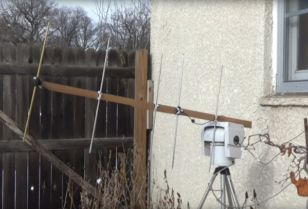
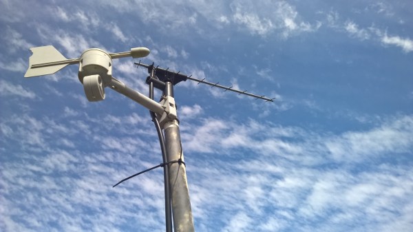
Pirates on these satellites have typically used them for illicit activities, and it is still illegal to use them for non-governmental or non-military purposes, so [Gabe] notes that he will only be receiving, not transmitting. The signals he is tuning in to are VHF transmissions, specifically around 220 MHz. That puts them easily within the reach of the RTL-SDR and common ham radio equipment, but since they are coming from space a more directional antenna is needed. [Gabe] quickly builds a Yagi antenna from scrap, tuned specifically to 255 MHz, and mounts it to an old remote-controlled security camera mount which allows him to point it exactly at the satellite and monitor transmissions.

From there he is able to pick up what looks like a few encrypted and/or digital transmissions, plus analog transmissions of likely pirates speaking a language he guesses to be Portuguese. He also hears what he thinks is a foreign TV broadcast, but oddly enough turns out to be NPR. These aren’t the only signals in space to tune to, either. There are plenty of purpose-built ham radio satellites available for any licensed person to use, and we’ve also seen this other RTL-SDR configured to snoop on Starlink signals.

Continue reading “Hunting For Space Pirates”

Lowering The Boom On Yagi Element Isolation

Antenna design can be confusing, to say the least. There’s so much black magic that goes into antennas that newbies often look at designs and are left wondering exactly how the thing could ever work. Slight changes in length or the angle between two elements result in a vastly different resonant frequency or a significant change in the antenna’s impedance. It can drive one to distraction.

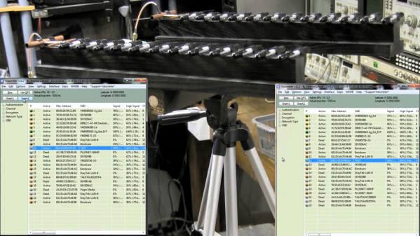
Particularly concerning are the frequent appearances of what seem to be dead shorts between the two conductors of a feedline, which [andrew mcneil] explored with a pair of WiFi Yagi antennas. These highly directional antennas have a driven element and a number of parasitic elements, specifically a reflector behind the driven element and one or more directors in front of it. Constructive and destructive interference based on the spacing of the elements and capacitive or inductive coupling based on their length determine the characteristics of the antenna. [Andrew]’s test antennas have their twelve directors either isolated from the boom or shorted together to the shield of the feedline. In side-by-side tests with a known signal source, both antennas performed exactly the same, meaning that if you choose to build a Yagi, you’ve got a lot of flexibility in what materials you choose and how you attach elements to the boom.

If you want to dive a little deeper into how the Yagi works, and to learn why it’s more properly known as the Yagi-Uda antenna, check out our story on their history and operational theory. And hats off to [andrew] for reminding us that antenna design is often an exercise in practicality; after all, an umbrella and some tin cans or even a rusty nail will do under the right circumstances.

Continue reading “Lowering The Boom On Yagi Element Isolation”

Umbrella And Tin Cans Turned Into WiFi Dish Antenna

There’s something iconic about dish antennas. Chances are it’s the antenna that non-antenna people think about when they picture an antenna. And for many applications, the directionality and gain of a dish can really help reach out and touch someone. So if you’re looking to tap into a distant WiFi network, this umbrella-turned-dish antenna might be just the thing to build.

Stretching the limits of WiFi connections seems to be a focus of [andrew mcneil]’s builds, at least to judge by his YouTube channel. This portable, foldable dish is intended to increase the performance of one of his cantennas, a simple home-brew WiFi antenna that uses food cans as directional waveguides. The dish is built from the skeleton of an umbrella-style photographer’s flash reflector; he chose this over a discount-store rain umbrella because the reflector has an actual parabolic shape. The reflective material was stripped off and used as a template to cut new gores of metal window screen material. It’s considerably stiffer than the reflector fabric, but it stretches taut between the ribs and can still fold up, at least sort of. An arm was fashioned from dowels to position the cantenna feed-horn at the focus of the reflector; not much detail is given on the cantenna itself, but we assume it’s similar in design to cantennas we’ve featured before.

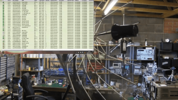
[andrew] hasn’t done rigorous testing yet, but a quick 360° scan from inside his shop showed dozens of WiFi signals, most with really good signals. We’ll be interested to see just how much this reflector increases the cantenna’s performance.

Continue reading “Umbrella And Tin Cans Turned Into WiFi Dish Antenna”

Quick Hack Creates A Visual Beep Alarm

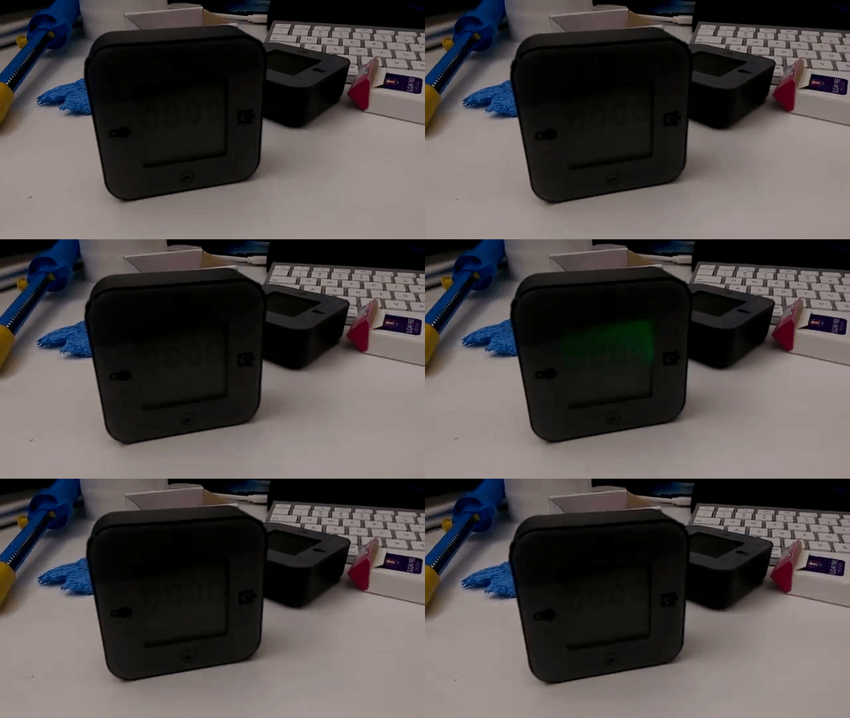
Sometimes a simple modification is all it takes to get something just the way you want it. The Ikea LÖTTORP clock/thermometer/timer caught [Mansour Behabadi’s] eye. The LÖTTORP  has four functions based on its orientation. [Mansour] loved the orientation feature, but hated the clock’s shrill beeping alert. Visual beeps or alarms can be handy when working with headphones or in a loud environment. With this in mind [Mansour] decided to crack his LÖTTORP open and rewire it to produce a visual beep for the timer function.

The clock is backlit, so [Behabadi] decided to use the backlight for his visual beep. Once the inside was exposed, [Behabadi] noticed that the buzzer’s positive terminal was wired to the red LED anode — a clever design choice, since the red LED is only used with the clock function. Simply removing the buzzer and soldering its terminal to the noticeable green LED provided the desired effect.

We meant it when we said he cracked it open. The screws were hidden behind the front plate, so the handyman’s secret weapon helped in reassembling the clock after this quick hack.

We’ve featured plenty of classy, unique, and ingenious clocks on Hackaday, so this modification is in good company.

Solving ISP Problem With A Homebrew LTE Yagi

We’ve heard reports that internet connectivity in Australia can be an iffy proposition, and [deandob] seems to back that up. At the limit of a decent DSL connection and on the fringe of LTE, [deandob] decided to optimize the wireless connection with this homebrew Yagi antenna.

Officially known as the Yagi-Uda after its two Japanese inventors from the 1920s, but generally shortened to the name of its less involved but quicker to patent inventor, the Yagi is an antenna that provides high gain in one direction. That a homebrew antenna was even necessary at all is due to [deandob]’s ISP using the 2300MHz band rather than the more popular 2400MHz – plenty of cheap 2.4GHz antennas out there, but not so much with 2.3GHz. With multiple parallel and precisely sized and spaced parasitic elements, a Yagi can be a complicated design, but luckily for [deandob] the ham radio community has a good selection of Yagi design tools available. His final design uses an aluminum rod for a boom, 2mm steel wire for reflectors and directors, and a length of coax as the driven element. The result? Better connectivity that pushes his ISP throttling limit, and no more need to mount the modem high enough in his house to use the internal antenna.

People on the fringes of internet coverage go to great lengths to get connections, like this off-grid network bridge. Or if you’d rather use a homebrew Yagi to listen to meteors, that’s possible too.

TDOA (Time Difference Of Arrival) Directional Antenna

tdoa-antenna-tutorial

We have posted articles in the past on directional antennas such as Yagi antennas used for transmitter hunting otherwise known as fox hunting. Those types of antennas and reception suffer from one major drawback, which is as you get close to the transmitter the S meter will go full scale. At which time the transmitted signal appears to be coming from all directions. To correct for this problem you need to use clever signal attenuators or change to a poor receiving antenna as well as tuning off frequency effectively making your receiver hard of hearing so that only the direct path to the transmitter is loudest.

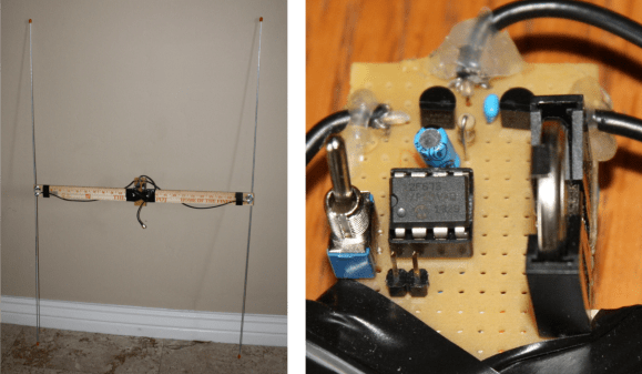
There is another popular type of antenna that you can build yourself called a TDOA which stands for Time Difference of Arrival. [Byon Garrabrant N6BG]  shared a short video tutorial on the functionality of his home built TDOA antenna. Effectively this is an active antenna that uses a 555 chip or, in [Byon’s] case, a PIC chip to quickly shift between two receiving dipole antennas at either end of a shortened yardstick. In his explanation you learn that as the antenna ends move closer or farther from the source a 640 Hz generated audio tone will go from loud to very soft as the antennas become equal distance from the source. This type of directional reception is not affected by signal strength. This means you can be very close to a powerful transmitter and it will still function as a good directional antenna.

The current circuit diagram, BOM and source code are all available on [Byon’s] TDOA page.

The reason [Byon] used a programmable PIC instead of the 555 for his design is because he wants to add a few more modifications such as feeding back the audio output to the PIC in order to programmatically turn on a left or right LED indicating the direction of the transmitter. Furthermore, he plans on adding a third antenna in a triangular configuration to programmatically control a circle of 6 LEDs indicating the exact direction of the signal. When he finishes the final modifications he can drive around with the antenna array on his vehicle and the circle of LEDs inside indicating the exact direction to navigate.

We look forward to seeing the rest of the development which might even become a kit someday. You can watch [Byon’s] TDOA video after the break.

Continue reading “TDOA (Time Difference Of Arrival) Directional Antenna”

Cheap Biquad Antenna Extends LAN Between Apartments

[Danilo Larizza] is sharing a network connection between a couple of apartments. They are not far apart, but they are also not right next to each other so a set of external antennas is necessary. He built this 2.4 GHz biquad antenna on the cheap (translated) just to test if it improved the signal before he tried to buy a proper antenna. It turns out to work well enough that this is all that he needs.

The antenna itself is about one meter of thick wire bent into two squares which are 31mm on each side. The coaxial cable going to the router connects to the center portion of this antenna. For a bit better directional reception he added some tin foil as a reflector. Since this is outdoors he used a food storage container for protection (the antenna is mounted to the lid, the body has been removed for this picture). The whole things is perched on a stake in a flower pot with proper line of sight to the other antenna.

We’ve seen a very similar design used for an NRF 24L01+ radio. If you need more details that [Danilo] posted that would be a good project to study.