[James] has been building a heart rate monitor using a very cool TI chip. He needed a way to test his device, and commercial ECG simulators, like all biotech devices, are absurdly expensive. [James] decided to build his own heart rate simulator, and in the process made a great tool and one of the most well documented projects we’ve ever seen.
Of course, if you’re building an ECG simulator, you’re going to need a good sample of a heart’s electrical pattern. To get this sample, [James] found an old army manual with a diagram of an ideal ECG pattern. [James] took this PDF manual, screen capped the diagram, and used a Python script to generate an array in C the Arduino could repeat over and over.
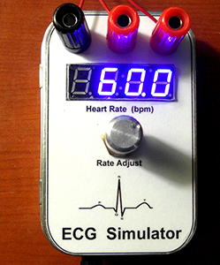
The rest of the build consisted of a D/A converter, a pot to change the heart rate, a very nice seven-segment display, and a few banana jacks to connect to [James]’ heart monitor. Everything is up in a git, including an amazingly well documented (87 pages!) tutorial for building your own Arduino heart simulator.


This is incredible, this will save a lot of money
He doesn’t have a heart-beat of his own to test it with?
Yes, many engineers don’t have hearts… Or is that engineer admin’s…
It’s a complete and utter pain in the ass to try to sense your own heartbeat while circuit bending (at least it has been difficult for me, so far). Any movement or shift in your electrodes can produce noise on the readout or in the data. It’s even more difficult if you’re not looking at real-time data.
Hell, certain medical grade EKG systems are a pain to work with. You’ve got to get every little environmental issue worked out or your tracings look like crap.
Good looking project. Eventually I want to make a cheap and simple EKG for my next deployment. This is going to help.
HA! That’s pretty funny.
Great point on testing while hooked up, I can see why that it would be a pain.
There’s also the safety side – working on a circuit coupled to your own heart can easily turn dangerous. Doesn’t take much to mess things up if you have a low impedance connection, which the EKG sticky pads provide.
Also, don’t tell the author, but I found a real EKG simulator in my local electronics surplus shop for like $5 :) I’m no expert in these systems but here’s a teardown and touch of reverse engineering: http://www.youtube.com/watch?v=rd_LrHytRs0
I wonder if James also has documented his work with the “very cool TI chip.”
Hi Mark. I’m just getting started investigation the TI ecg front-end chip. However, when I finish the heart monitor project, I promise to publish a boffo tutorial on it. Cheers, Jim Lynch
Just starting the TI ADS1293 project; but I promise that when I’m done, I’ll publish a boffo report!
GATTACA! This is exactly what he needed too fool those pesky eugenicists!
Having built a couple of heart monitors a few years back (one using the then brand new ADS1298 (and later ADS1298R)), this looks to be of limited utility for evaluating the properties of various ECG front ends. A human body impedance model for ECG purposes is really damn complex, if you’re trying to account for the “hard” parts of the system–dealing with mismatched impedances from the leads, rejecting electrode potentials, tuning the right leg drive circuit, preventing amplifier saturation due to a faulty electrode causing the impedance of one lead to vary over time (especially a problem when doing active testing on a treadmill, or when using non-standard ECG coupling topologies), cancelling a shifting DC baseline on the differential signal, etc…
Making an ideal signal is easy. Making something that responds the way an actual patient does in the real world is hard.
Thanks for your cogent reply. You just described why ECG simulators can be so expensive. For my purposes (personal DIY project) a 3-lead simple ECG signal generator is sufficient to let me learn about and experiment with the Texas Instruments ADS1293 chip and its evaluation board.
Luckily, I was able to use myself and my friends as guinea pigs for experimentation. This, of course, is completely safe if you take a few reasonable precautions (namely, isolation from mains equipment). Since most testing ended up being done with a mobile laptop, this wasn’t a problem, but otherwise I used either the bluetooth interface on my ecg (battery powered!), or used a USB isolator for the physical interface.
While obviously not rigorous in any sense, it helps illuminate the issues you have to deal with in the real world—myoelectric noise, to improper electrode placement, 60Hz noise picked up by the human body (not a bad antenna!). The issue with this is that it does not give you a reference test for repeated measurements. Luckily, getting a basic ECG to work is dead simple (just a differential amplifier with a 10-100x gain, high pass filter with flat freq. response in the pass band and active DC bias cancellation). The only tricky parts are the input filter (many input filter designs can murder the CMRR of the instrumentation amplifier, or be improperly matched to the impedance of the system). So, the simulator can help to verify that the ECG amplifies with the correct gain and minimal distortion, but that’s the easy part, IMO.
Sorry to sound overly critical–when I was working on this stuff, I was deparate for a patient simulator to verify my designs, since they were way trickier than conventional designs (specifically, 2-3 lead fabric electrodes integrated into a shirt, with a mostly-capactively coupled differential input filter—they need large surface area to get low resistance, but this introduces tons of additional noise. Also, the contact impedance of the sensor will vary by orders of magnitude, which makes it really easy to throw off the amplifier. fun times)
Dear Slanderer,
I am a design student from the Netherlands and I am working on a similar design (wearable ECG embedded in fabric). Would you be willing to contact me and possibly share some information about your implementation (and the problems you faced). It will be for purely educational purposes. You can reach me at wearable.ecg@gmail.com
Kind regards, Vleer Doing
In order to build to that “real world patient”, it is incredibly helpful to have an ideal baseline to work from.
James Lynch: Do you think your ECG monitor would at least theoretically be able to automatically sense variations in T-wave (peaks) and P-waves (reduction in size)? This would be fantastically useful to hyper/hypo-kalemics as a means of monitoring potassium levels, which can’t otherwise be accurately read.
EccentricElectron: Of course it could. These TI front-end chips send the signal continuously via an SPI interface (that is where I intend to transformer-isolate the thing). Receiving that signal would be an embedded microprocessor. I have a Arduino Due and a Raspberry Pi in house, I’m shading towards the Pi since it supports graphics and wireless so well. It certainly could perform the signal processing algorithms you described.
Well short of shaving a dog this is the best way to test his ECG, very nice.
Finally, an awesome project, put into an altoids tin, and not being ruined because altoids tins look like ass. Very cool, and good idea too. Death by electrocution is my worst fear…