This pulse oximeter is so simple and cheap to build it’s almost criminal. The most obvious way to monitor the output of the sensor is to use an oscilloscope. The poor-man’s stand-in for that is a sound card, which is what [Scott Harden] demonstrates in his write-up.
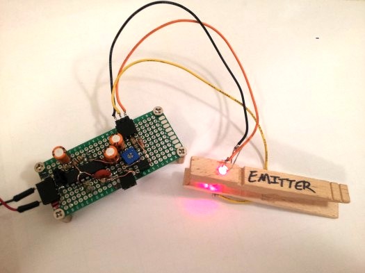
It uses a concept we’ve seen a few times before. The light from an LED shines through your finger and is measured on the other side by a phototransistor. It’s that light grey plastic thing you see on a patient’s finger when they’re in the hospital. [Scott] went with a common wooden clothes pin as a way to mount and align the sensor with your finger. It is monitored by the simplest of circuits which uses just one chip: an LM324 op-amp. There are three basic stages which he explains well in the video after the jump. The incoming signal is decoupled before being fed to the first amplifier stage. From there it is fed to an adjustable low-pass filter to help eliminate 60Hz noise from AC power in the room. The last stage amplifies the signal again while using another low-pass filter in parallel.


This is NOT AN OXIMETER. Oximeters use two photodiodes (one each which is sensitive to either oxygenated or deoxygenated blood). This is just the pulse part.
+1 Oximeters will output apparent blood oxygenation “sats”.
This is a heart rate meter.
Damn, I was excited by a possibility to cheaply monitor spO2 during a cardio workout :( For a simple heartbeat detection, my elliptical trainer already has contacts on the handles, no need to torture the finger with a clothes peg. (But, oximetry would be a strong enough reason to do that.)
This is a photoplethysmograph. A pulse oximeter is essentially two photoplethysmographs (two different wavelengths of light: 660 nm and ~900 nm). Oxygenated blood and deoxygenated blood each absorb at different wavelengths.The difference between the two waveforms indicates the ratio of oxygenated to deoxygenated blood. I’ve implemented a non-invasive pulse oximeter and it is non-trivial to achieve accuracy independent of skin color, calluses, bones, etc.
For anyone reading this years later who is building a pulse oximeter and is now confused because this comment doesn’t match any circuit diagram or datasheet for a pulse oximeter or integrated chip you’ve ever seen, the claim that pulse oximeters use two photodiodes with tuned light sensitivity in the IR and red bands doesn’t appear to be true today. I can’t say it wasn’t true at some point in the past but having looked over numerous circuits and disassembled medical pulse oximeters all of them only use one photodiode. Some use an opt101p instead, others use a variety of photodiodes, but only one per oximeter. As for integrated chips, the AFE4490 uses a single photodiode. As does the MAX30100.
Taking the OPT101 as an example, that chip exhibits response from 650-950nm that is entirely adequate to detect both oxygenated and deoxygenated blood following the amplification that’s done in those circuits anyway. Maybe there’s some specialty lab equipment that never made it to ebay for me to buy and take apart that does use two photodiodes, but, so far as I know, pulse oximeters use one and only one photodiode. Because there’s no reason to use more. It’s far easier (and more cost effective) to make up any loss in sensitivity in the red or IR bands by just using a brighter LED for that band.
Can confirm this, most Nellcor-compatible pulse oximeters (very common) use two LEDs and one photodiode.
still not bad for some common parts and a clothes peg! LM324 has to be up there with the 555 & LM317 in terms of is versitility and simple form.
Yeah, but adding one more diode stolen from a tv remote, and turning each on separately would allow you to get actual O2 data, not just pulse.
Myself, i just kept the disposable pulse-ox sensor they taped to my finger the last time i was at a hospital.
+1
@Quin: What would you have to include to implement rapid switching between two light sources? You’d have to eliminate the capacitive decoupling on the input to make it quantitative (one of the things that allows tremendous gain at minimal complexity), control when each light source fires (wich adds complexity), determine when to measure absorbency readings synchronized with illumination sources (further adds complexity), and report the output as an amplified ratio of the difference between these two readings (likely requiring two separate amplification chains and/or a rapidly switching amplifier configuration, perhaps with lowpass-filtered output as the reference voltage). I would argue that making a pulse oximeter is significantly more involved than “adding on more diode stolen from a TV remote”. By the time you start adding oscillators and microcontrollers, we’re far away from a single-chip 50-cent device.
This is how I did it: http://eet.etec.wwu.edu/zimmerm/
Don’t bother, there’s nothing actually there.
Are you looking at the same site as me? I’ve found code and everything on it. Can’t look too much now as I’m at work, but there seems to be plenty there.
@Mental2k The code comments might get a little sparse and I can’t remember everything myself at this point (written quickly, with lots of coffee). The proposal and description documents might be interesting if you’re thinking of starting a project. I think it would be cool to do something similar but with reflected light (sensor and LEDs on the same side) rather than transmitted. Another angle that would be interesting is a SOC implementation (like the Cypress PSOC chips).
Does it have to be rapid? Few times a second, maybe a few dozen, would be fine I’d think. Say 10x the human pulse rate ought to give consistent data between samplings from either source.
Switching 2 LEDs on and off isn’t hard. Neither’s syncing the results up. It’s simple in software. The switching rate for all the components would be low enough there’s no capacitive problems to worry about. You’d perhaps need to scale the IR / red LEDs against each other, how relatively bright each one is to the sensor, to be able to get O2 readings. You could do that with a few humans and an already calibrated unit.
A 3D printed finger grip and case would add a professional finish to this project.
Great, we got the look-at-meee idiot managing to put an offtopic line on 3d printers…
come fetch your prize, retard…
Are you going to 3D print his prize?
Unfortunately we cannot print common decency yet, but it’s there on the list we swear it!. You’ll have to live with being a douche for a little while longer.
Love these sats probe hacks. Hospitals throw them out every single day, by the bucketload. Nellcor/massimo etc charge about $80 each for the probes. Thats two LEDs, a sensor and some wires. This is where your health dollars go. That and 75$ plastic giving sets, and $80 apnoea monitor leads. Etc.
I think you underestimate how difficult and expensive it is to get even medium-risk healthcare technology to market.
It costs a few bucks for the parts and labor and the big $ to get the markings that say “FDA approved medical device” and all the testing to make sure its accurate (the last thing you want is an emergency or ICU doctor doing the wrong thing because they are getting incorrect readings from a pulse oximeter or other medical sensor)
Understand that, but how long would it take to pay back R+D/compliance costs when ytou are selling an item for 30 times what it costs to make?
Unfortunately in a capitalist system such as that in the US, if the state wants competition in a single-buyer market it’s going to have to fund its creation. Which is apparently taboo in the US since the thirties.
Yeah and in socialist system, you do not even get the basic technology everyone else in capitalism has for decades.
Been there lived through that. E.g. in eighties even the basic Brufen (Ibuprofen, Advil) had to be smuggled in from western capitalist world! Thanks God for capitalism.
BTW, it is NOT competition which drives the cost of health care, just the opposite is true.
It is the gubmint insane regulations which drive the costs through the roof. That and lobbyist efforts to beat the competition using regulatory tools. It is called crony capitalism of fascism.
Nice job!
You should have it calculating the O2 level aswell.
found a great description here:
http://www.howequipmentworks.com/physics/respi_measurements/oxygen/oximeter/pulse_oximeter.html
I’m definitive going to try this myself :-)
Not entirely related to this but http://ewh.org/ is worth a look at if you’re in to charity work and medical engineering.
Great use of low cost components. You might try battery power to reduce 60 Hz noise and couple the output back with an optoisolator or power transformer to completely isolate the circuit. The 60 Hz noise is mostly from the power supply and the scope.
You also might try harvesting your optics from an old CD player or two CD players for double shine through.
If you insist on using AC power you can use a power transformer as a common mode choke to eliminate the AC. (http://en.wikipedia.org/wiki/Choke_(electronics)#Common-mode_choke) Simply feed the DC plus 60 Hz noise through one end of both coils of an transformer and pick up the DC on the other ends. This will clean up your DC by choking off AC.
How come I see 4-5 capacitor on his corcuit and only 3 on the diagram?
And also what is the value of the resistor on the pre-amp?