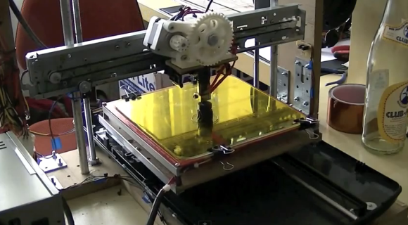
These days it’s super-easy (not super-cheap) to go out and buy a 3D printer. But if you’ve got the mad skills like [Mario Lukas] maybe you can build a 3D print using a bunch of scavenged parts (translated). He’s published six posts on the build, and put together an overview video which you can watch after the break.
A pile of salvaged parts were found in a scanner and four different printers. He’s also powering the thing with an old PC PSU. The hot bed and extruder are brand new, which is a wise investment. We’re not sure about the threaded rod and bearings but we’d bet those are new as well. When it came time to work on the electronics he chose an Arduino board as the go-between for the printer and computer. It uses four stepper motor driver boards to drive the axes. Connections can be a bit complicated and he actually ‘smoked’ one of the boards during the development phase.
One of the mechanical build posts shows a belt routed in a T-shape. We wonder if it’s function is similar to what this H-bot style printer uses?


I’m looking forward to reading through this in depth. I have two printers pulled apart at home already with plans to do this exact same thing.
I’d be careful. Re-using servos from printers is a great way to save money. But using scrap for the frame, well that may not be worth your time. The results in the vid look ok from what I can tell, but what you will quickly find is ANY flex or drift will present itself in the part. Even off-shelf makerbots and such riding on threaded rods for z axis have some XY drift as Z moves up, causes layer variation. Acceptable for most applications, but considering how small the parts have to be for 4″x4″x4″ build window, even .005 is easily visible as a decent % of error. Most 3D printers seem to suffer from the frame being under-built.
To truly build it out would be rigid smooth zero-slop rails on each axis with lead screws or belts as non structural adjustment-only. Not sure why more people don’t just start with a small milling machine or at least scavenge parts off industrial equipment which is precision machined for this task.
Hmm, I’d expect mills to be built for torque rather than speed. But other than that, are there any other disadvantages to using a mill with a plastruder? Does printing slow affect the quality?
Still, the output of this build is respectable. Well done I say.
Another point to consider when using salvaged parts. What happens if you need to get hold of another one? Perhaps you’re wanting to make a second printer or repair a broken motor. If you can’t find the original item that you used to take parts from, it’s going to be a tall order to find that exact part you’re after!
You go out and get more junk? Actually stepper motors are standard frames so they are easy to replace. The machine in this article uses a pancake motor, and a NEMA 17 that I could see. No one repairs stepper motors, well some folks try, but their results have about a 10th the power of the original unit. Something about lacking a million dollar machine for the final assembly I’m sure… In other words, one does not simply repair a stepper motor.
I converted a CNC machine (MAX NC15) to a 3D printer by just adding an extruder and a heated bed. While it prints nicely for some certain parts, but then I decided to print parts to make a real reprap machine. The reason is: 1. The noise generated by this machine is too much. 2. It’s way too slow. I can only print as fast as 15mm/s. Higher than this, chance of loosing steps and chance of getting a broken parts after it has gone through 4 hours of printing with no problem. 3. The power that goes to the heated bed (100W on mine) and extruder (50W on my setup) can be quite wasteful with print too slow. 4. Somehow backlash is not well compensated in the software I’m using (SkeInforge). Sometime it seems working but sometimes it’s not. Belt and dedicated reprap seem working better.
35.4 inches per minute rapids is pretty slow. Slap some servos onto that puppy and bring it up to maybe 200? That would be making a silk purse out of a sow’s ear.
With that 15mm/s I already fear of the machine tearing its brass ACME nut apart. When it prints the filling, the X & Y go back and forth a lot. Before I started printing, the X axis didn’t have any lashes. Now after spending sometimes on it, I got about 0.005″ backlash. I can’t imagine how long the 1/2″ brass nut would last with 100mm/s speed.
Btw, how fast would you need to mill aluminum, or carbon fiber, especially for a desktop CNC machine? With a 1/2HP spindle, I cut aluminum at 5 – 10″ per minutes just to be safe and not breaking cutter (1/8″ cutter)
To increase performance the first place to make a change is lead drive screws. Ball screws or multi-start leads are the preferred choices. Companies have to make a profit though so they don’t always equip their products with the best things. In the meantime you might want to think about some lubrication on those wearing parts. Real milling machines have oil pumps they take the matter so seriously. Maybe you are oiling but the oil you are using is ineffective? I use chainsaw bar oil as way oil. It works pretty good. Saw bar lube is easy to get too. Vactra is a well known name brand product for the job though. Light oils and or motor oils should be avoided. Your mill will run better slathered up with some good sticky oil. Brush it on.
Thanks for the advices pcf11. I have thought of adding ball screw but thinking maybe it’s better just to build a bigger machine. It uses 4 start ACME lead screws. I use white lithium grease for lubrication. Not sure if it’s good or not, but it’s sure sticky and stay on the screw. :). Didn’t know about the oil pump thing. Have to check those chain saw and saw bar lube at local hardware store next time I’m there. Thanks
I’ve worked with a lot of CNC’s, and let me tell you they can be SCARY fast, especially considering the amount of mass flying around. It’s all about how powerful the servos are, and how rigid the frame is.
You obviously don’t know what a MAX NC15 is. Scary small is one way to describe it :)
I think a frame that flexes is one major problem since the extruder assembly is meant to move fast and stop abruptly that can cause flex just due to that mass causing a force on the motors which is transferred into the frame. You can easily check if thats the case by simply reducing the speed of the print and see if there is a major difference. On the other hand I haven’t seen many people build their 3d printers with great precision, most frames are wooden which doesn’t give that much accuracy even if you cut it on a machine and I’d like to see what kind of rods people are using for their linear slides. There is a huge difference between just a hardened steel rod and a precision ground one, of course it shows in price too. If you compare the accuracy of the actual fram to a milling machine there is a lot more work that goes into a mill to make it accurate than meets the eye. For example most linear motion components are hand scraped or precision ground to get them to actually move straight and even the table has to be scraped b/c when you machine it the heat introduced into the part throws it off by a tiny amount. That said I’d love to see someone build a printer with a super rigid frame and have all the mounting holes and what not done by a high quality CNC or a skilled machinist so the tolerances are much closer. I’m in the process of designing my own 3d printer now and will be doing some FEA simulations to determine where my frame needs to be stronger and will machine it out of aluminum for the above listed reasons.
Most of the reprap based 3D printers I’ve seen used 8mm smooth rods for the rails. These can flex quite a bit. I’ve finished printing & building a printRBot from my MaxNC milling rep-strap machine. The printRbot also uses 8mm rails. Seeing how the extruder head vibrates just because of the Y axis moving make me really nervous. With all settings (layer thickness and extrusion width) the same, the quality of the print from a printRbot is considerably just a merely less smooth than the prints come from the much more rigid max NC machine. In another hand, with no backlash it creates a much straighter part. With my limited experience, the quality and consistency of the extruder & filament play a lot more important roll in the quality of the part than the flimsy frame.
Though I still plan to print a much beefier printRbot base (Wallace machine) with a 12 or 16mm rails instead of the flimsy 8mm rails.
The T-shaped belt path mentioned in the summary is completely unrelated to a H-belt system.
A H-belt system uses 2 fixed motors connected to a moving carriage using a timing belt in an H-shape to move the carriage in X and Y directions.
The T-shaped belt design in this case is one fixed motor connected to 2 threaded rods for the Z axis, the 2 bearings are for belt tensioning/improving the belt path.
I was just going to say something. It really seems that the quality of posts has been sliding, sometimes I find myself asking if the HaD author even bothered to read the article.
Its quite clear that the “T” shaped belt routing is just to drive the two Z rods at the same time with one motor. Similar to some of the original Mendel iterations.
Mike Szczys has almost three times as many posts as any other HaD author past or present and it is increasingly clear that no one checks his work.
And while it is a silly thing to notice, Szczys doesn’t have any real vowels in it? o.O
ZOMG!! His name is a hack!! O_____O
> And while it is a silly thing to notice, Szczys doesn’t have any real vowels in it?
If you want a real treat, check out how he pronounces his name in the videos he’s made.
By my ear, it goes between “seeks”, “psychs”, and “stich”
STISH. mind-blown
Maybe it’s fatigue, but I’m guessing they rely to some extent on the text accompanying the tip someone sends in. I don’t expect them to dig into the details of everything they post.
it would be insanely time consuming to attempt to become experts in every single item that we share. We count on our readers to make observations and bring insight. Hopefully they do it intelligently and without being assholes.
Work sucks don’t it? You must be new to this Internet thing. You’re going to run into a lot of assholes here!
Now he can just use this to print another 3D printer…
That’s what we call a “rep-strap”. Usually you build a low-quality/temporary printer from junk parts to avoid the chicken and egg issue with self-replicating 3D-printers… But… why? This one does not appear to be low-quality, it looks like it works just fine.
Thats some fantastic output given the components used in that design
your help would be really appreciated