We’ve been following the work of [Andrew Holme] and his homebrew GPS receiver for a while now. A few years ago, [Andrew] built a four-channel GPS receiver from scratch, but apparently that wasn’t enough for him. He expanded his build last year to track up to eight satellites, and this month added a Raspberry Pi for a 12-channel, battery-powered homebrew GPS receiver that has an accuracy of about 3 feet.
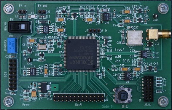
The Raspi is attached to an FPGA board that handles the local oscillator, real-time events, and tracks satellites automatically. The Pi handles the difficult but not time-critical math through an SPI interface. Because the Pi is attached to the FPGA through an SPI interface, it can also load up the FPGA with even more custom code, potentially turning this 12-channel receiver into a 16- or 18-channel one.
An LCD display attached to the FPGA board shows the current latitude, longitude, and other miscellaneous data like the number of satellites received. With a large Li-ion battery, the entire system can be powered for about 5 hours; an impressively portable GPS system that rivals the best commercial options out there.


It would be interesting to see how easy it would be to add GLONASS support to this receiver. From what I have been reading, the frequencies are “relatively” close, so it might be possible with a few tweaks to the front end, and as said, a software update from the Raspberry Pi.
GLaDOS support would be more impressive.
Or GoNaD support
i second that
I dunno, the potato would make it rather heavy, at least for expectations people have in portable devices these days. Maybe back in the 80s…
While GLONASS and GPS codes are “relatively close”, you would need separate RF channels and separate software to decode the signals. The first place you could start sharing hardware/software would be after the signal is successfully demodulated.
SDR does not work that way. You’re limited only by processing power to the amount of bandwidth (and thus channels) you can work with.
They’re ~25MHz apart so (GPS is centered on 1575MHz GLONASS is on 1602MHz) so depending on the Radio front-end he’s using he may need a separate RF system.
Or just program the synthesizer on a slightly different frequency.
I would love to get my hands on a working unit. I say working because my hands shake to much to solder anything these days. So I have now concentrated on the programming end of things.
pretty impressive …i have two questions thought:
wouldn’t a slightly bigger fpga integrating a virtual processor be more practical that a whole pi?
and i was also wondering if someone ever fooled around with pcb (fractal) antennas and gps to make a build like this more compact..
Depends on the cost. From what little i’ve seen, that usually drives the price of the fpga board up more than 25-35 USD. would definitely love to see one with a pcb fractal antenna.
the intresting thing about this is that all commercially available gps chips have some security functions in there that shut down the device when moving faster than some few 100 km/h. This is to prevent pepole from building DIY cruise missiles / rockets or fast drones or things like that. whith a open GPS receveir it is possible to ignore these things.
nice work btw. that looks really like a lot of fpga-timing optimization.
Next week,
3d Printed Cruse Missile with raspi brain!
Can’t wait!
and opencv to identify targets with the official rpi camera that just came out!
Raspi / FPGA will then be regulated
Aren’t big FPGA already export controlled?
Probably the biggest problem with this would be to get the print filament for the “payload” :-)
en wiki:
In GPS technology, the phrasing “COCOM Limits” is also used to refer to a limit placed to GPS tracking devices that should disable tracking when the device realizes itself to be moving faster than 1,000 knots (1,900 km/h; 1,200 mph) at an altitude higher than 60,000 feet (18,000 m).[2] This was intended to avoid the use of GPS in intercontinental ballistic missile-like applications.
if you can afford building a drone going 1900 km/h, you wouldn’t really be bothered by this limit.
If this were true, then your average jet airplane would be with GPS before it even takes off the ground.
The limits of the commercial GPS receivers are to reduce cost and the number of correlators needed on chip. The limits also allow tuning of the filters on chip to be more accurate under lower system dynamics.
It is true, but the poster was off on the exact limits. GPS receivers are required to shut off if at an altitude greater than 60,000 feet, and moving faster than 1,000 knots (1,200 mph). Military receivers are excluded from these restrictions (known as COCOM restrictions).
GPS receiver manufacturers sometimes imposes even lower limits, one common is to misinterpret COCOM with OR instead AND. This make some headaches to amateur ballon , they move slow but easily get over 60.000 feet.
The way this spec ( 60000 ft AGL && 1000 knots ) is usually implemented is just shutting down if it’s going faster than 1000 knots. Honestly, I don’t know of too many hobbyist projects outside high power rocketry that would exceed that spec.
This DOES NOT rival commercial products. Sorry. But it is impressive! “The best fix so far was ±1 metres at a very open location using 12 satellites; but accuracy is typically ±5 metres in poorer locations with fewer satellites.”
How accurate are comparably priced commercial products?
Usually 5-10 metres for GPS systems in cars.
I think there’s software correction in the UI so that your car doesn’t drift outside the road markings.
No, the *mapping* is corrected to appear that you are still on the road. This makes the average person think the device works better than it really does.
A latest generation ublox or sirf gps will get you less than 10 feet accuracy even without a clear view of the sky.
Not true at all. I have driven off the shoulder on a road and my GPS clearly showed that I was driving parallel to the road, but not on it.
I once had a file with a track from Sirf Star III based device. It was rather “interesting”, showing that I moved over the rooftops and so on.
I recorded it while rollerskating, the GPS device was in my backpack (and I definitely remember, that I haven’t done any spiderman-like stunts). Biggest error was about 30meters.
Also, see here: http://vitus-wagner.livejournal.com/195317.html (but the GPS model was not specified).
As for the car GPS units, I strongly suspect that they use both inertial navigation and GPS signal.
I wonder if two of these could implement DGPS.
In theory, DGPS sounds simple – you only need two GPS-enabled devices (one fixed and one mobile) and some means of communication between the two. Many of the positioning errors are not caused by the receiver, and are fairly constant over large areas. So by taking the error detected by the fixed device, and transmitting it to the mobile device where it is subtracted, you get a much more accurate result.
Out of curiosity, I did a bit of Googling a while back to see if anyone had successfully done it with common, inexpensive GPS modules. I only found one attempt, I think it was on the Parallax forums. It was a failure, accuracy got worse, and the reason could not be determined. IIRC it was suspected that the modules were tracking different sets of satellites, and therefore were subject to different errors that could not be differentially eliminated; however, the modules used didn’t provide enough info to test or fix this.
With this GPS you have access to, well, everything. Making a GPS from scratch is no small feat, to be sure. But if it could also provide a relatively inexpensive DGPS capability to hobbyists where there currently appears to be none, then that would be awesome.
I’m no GPS expert, so please correct anything I’ve stated that is inaccurate. Especially if DGPS has been successfully hacked, I’ve love to see a link to that.
This would only work if the jitter is identical in both coordinates and the same moments in time for both devices. The reason for the worsening would be actually compounding the jitter because they would not be exact, though I would expect a net-same effect assuming random directional jitter.
DPGS works by using the individual information from each satellite. Then the atmospheric effects (and other effects) can be corrected.
Correcting for error after the final solution for (x,y,z) is the wrong place to apply the correction because different satellites are introducing error in different directions.
I’d be more interested in running a lock on the L2 band as well to do in-place ionosphere correction.
Yes, though I believe all L2 is presently encrypted. NovAtel have a (secret) algorithm they use interpret L2 timing without having to decrypt it, and hence measure the difference between bands to self-correct. Someone else could therefore do the same thing, but it’s not as simple as “just look for the L2 signal”.
DGPS is quite possible when you have access to individual timings.
The other thing you can do, which would be great for UAVs, is calculate velocity directly, rather than simply as the difference between two final positions. Or, if using successive positions, skip the difference whenever a satellite is added/removed from the fix, or when jumping a cycle (assuming the calculation uses phase locking). OTS GPS chips may or may not do this, but I have seen UAV code that takes velocity from position data, then filters it, rather than asking the GPS receiver for it directly.
My dad is a land surveyor and this is exactly what we do with our industrial units. One is setup as a static base station and the other is a rover. The base station is set on a known point and calculates the difference of the measured position from the known position. Then the difference is sent to the rover via radio (433mhz band I think) where the rover position is corrected. We use a pair of Topcon Hiper SR’s (GPS and GLONASS) in an RTK setup and regularly get accuracy from 15mm – 20mm. But this isn’t the only type of DGPS.
Many coast guards operate DGPS stations over the VHF band. With the proper modem these signals can be easily fed into many types of GPS. We have an older unit that contains a serial port specifically to accepts these and other DGPS modems. Have a look at http://www.ccg-gcc.gc.ca/eng/CCG/DGPS_Home the DGPS protocol is fairly well documented here and on other nautical websites.
I once talked with another surveyor and his GPS would receive it’s corrections over the internet via a cellular modem. I never researched this method because according to him it was very problematic.
What would be interesting and useful to my dad and me would be an L1/L2 channel GPS receiver that can record to a Rinex file. This is how we set points whenever reliable backsights are not available. Sirf chipsets are capable of outputting Sirf Binary which can then be converted to Rinex. The problem though is that Sirf chipsets are only capable of recieving the C/A code of the L1 channel.
Hi, I work for a surveying equipment dealer and use the GPS that receives corrections over the mobile network regularly. It’s pretty darn good. Got 5mm accuracy in the car park last week with a Topcon GRS-1. Obviously won’t work where you can’t get a phone signal.
RTK is pretty great. Very clever using the phase of the carrier to calculate the distance between base and rover.
FWIW, this was used by forestry surveying companies back in the ’90s, in combination with traditional methods.
Dam it. I want to know where I’ve been when I am abducted by aliens!
Wait a bit… I’m still working on the Starfleet ship tracking system :P
This is a great piece of work. I am awed by his tenacity to keep at that project and refine it. The results are outstanding. Any aspect of this, RF smd pcb design, digital smd pcb design, sw, all are first rate. Prob all done in his garden shed (as a lot of great UK projects are done).
Very nice…if only the government wasn’t intentionally degrading the signal and screwing it all up, this thing would probably be accurate to under a foot.
They haven’t intentionally degraded the signal since 2000. Newer GPS satellites don’t even have the capability (SA). What civilians don’t get is access to the encrypted, higher precision P(Y) signal.
Really? I did not expect the military/secret services to permanently give up this possibility.
Next step… Sub meter rtk GPS
http://www.rtklib.com/rtklib_beagleboard.htm
Is anyone able to reach the article?
±1 meter resolution? I think it is ±1 meter accuracy.
Very cool and interesting! I’d like to see L1/L2 GPS & GLONASS. Then play around with RTK corrections.
Interesting read.
Reading the above I think my assumptions about GPs modules are wrong. I thought a 3m accuracy means the screen will give you coordinates that are anywhere within a circle of radius 3 m from that actual location. Thus is I know a spot on the earth is at (X,Y,Z) = (0,0,0) (explanation purposes only ) then the reading on the GPS at this spot could be (+-3,+-3,+-3) is this correct?
Then is the error random ?
Could you stay still and do successive approximations on the valves received and end up getting more accuracy? I’m guessing not or the reading son the GPs screen would fluctuate and everyone would be approximating.
Last question then. If I take my GPS device and put it on the (0,0,0) spot and adjust the displayed value so it reads 0,0,0
if I then moved 20 m in the X direction would it accurately and repeatable show I’ve moved the 20m ? And what would the error be on this ? I have an application where I need mm accuracy on where something is relative to another thing. So if I used two Arduino GPS shields and calibrated them to read the same at point A can I then move off to position B with the other GPS and it’ll give me mm accuracy relative to position A ? Looking for the discussion above it looks like this is possible but the error changes so the GPS at point A would need to be compared to the known coordinates for point A and these errors sent to GPS at point B to calculate point B’s position. This is very do able for me as I’m only mapping point A to point B over an area of maybe 100 m by 100m. Can anybody suggest what mm accuracy I could get doing this with standard GPs Arduino shield’s ? Thanks fellas…