So far we have discussed the basics of CAN, in-vehicle networks, and protocols used over CAN. We’re going to wrap up with a discussion of CAN tools, and parts to build your own CAN hardware.
Wiring
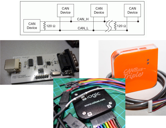
Unfortunately, there’s no set standard for CAN connections. The most common connector for high-speed CAN is a DE-9, with CAN high on pin 7 and CAN low on pin 2. However cables will differ, and many are incompatible.
CAN needs to be terminated, preferably by a 120 ohm resistance on either end of the bus. In practice, you can stick a single 120 ohm resistor across the bus to deal with termination.
Tools
A good CAN tool will let you transmit and receive CAN messages, interpret live data using CAN databases, and talk CAN protocols. The tools with this feature set are proprietary and expensive, but some hacker friendly options exist.
GoodThopter
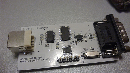
Based on [Travis Goodspeed’s] GoodFET, the GoodThopter by [Q] uses the Microchip MCP2515 CAN to SPI controller to access the bus. The open hardware tool lets you send and receive messages using Python scripts.
CAN Bus Triple
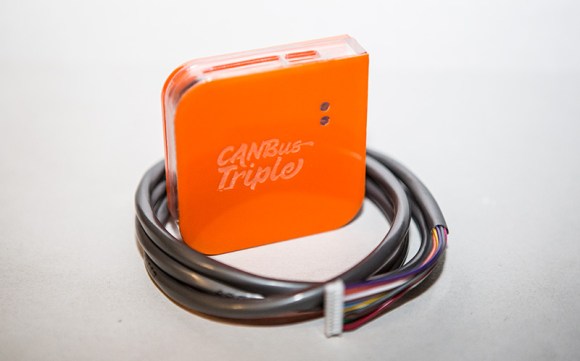
The CAN Bus Triple device provides an interface to three CAN buses, and can be programmed in an environment similar to Arduino. The open source code provided lets you muck with the second generation Mazda 3. Unfortunately, the hardware does not appear to be open source.
Saleae Logic
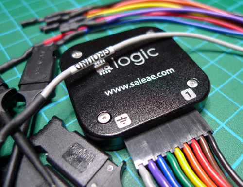
It’s not open source, but the Saleae Logic is a very handy and cheap tool for looking at CAN buses. It can capture, decode, and display CAN traffic. This is most useful when you’re building your own CAN hardware.
DIY
The Parts
If you want to design your own hardware for CAN, you’ll need two things: a CAN controller, and a CAN transceiver.
The CAN controller generates and interprets CAN messages. There’s many microcontrollers on the market with built-in CAN controllers, such as the Atmel ATmega32M1, Freescale S08D, and the TI Tiva C Series. When using a built-in CAN controller, you’ll have to use an external oscillator, internal oscillators are not sufficiently accurate for high-speed CAN. If you want to add CAN to an existing microcontroller, the MCP2515 is an option. It’s a standalone CAN controller that communicates over SPI.
The transceiver translates signals from the controller to the bus, and from the bus to the transceiver. Different transceivers are needed for high-speed and low-speed CAN networks. The NXP TJA1050 works with high-speed buses, and the ON Semi NCV7356 works with low-speed, single wire buses.
Dev Boards
There’s a ton of development boards out there featuring microcontrollers with a CAN controller. The Arduino Due‘s SAM3 processor has a controller, but there’s no transceiver on the board. You can pick up a CAN bus shield, and the Due CAN Library to get started.
The ChipKIT Max32 is similar to the Due. It has two CAN controllers, but you’ll need to provide external transceivers to actually get on a bus. Fortunately there’s a shield for that. The ChipKIT is officially supported by Ford’s OpenXC Platform, so you can grab their firmware.
That concludes our discussion of CAN Hacking. Hopefully you’re now ready to go out and experiment with the protocol. If you have questions, send them along to our tip line with “CAN Hacking” in the subject, and we’ll compile some answers. If you liked this series and want to suggest a topic for the next set of posts we’d love to hear that as well!


DUDE! You got to start using breaks!
Seriously, a break right before the Wiring section would be best. Please.
Looks like they connected the saleae wrong
They didn’t, grey wire is ground, as you can see on the wire label. I suppose it would be more logical if black one was ground, with channels color-coded same as resistor colors but hey, it’s Saleae(‘s) logic. :)
BTW, very nice clone, works with SL software&driver, but costs $9 : http://www.banggood.com/USB-Saleae-24M-8CH-24MHz-8Channel-Logic-Analyzer-Latest-Support-1_1_15-p-74101.html
and what about inside ? is circuit same ? dave from EEVBlog teared-down original…
My understanding is that they all use the same Cypress chip, so whether it’s a Saleae or a USBee is just a matter of the firmware. Now the ancillary components are probably worse, but my knockoff works just fine.
Yup, same Cypress chip. Isolation chip is also present.
Does anyone know the difference/compatibility with the BMW iBus and standard CAN? I’ve got a USB-iBus adaptor but wanted a dev board that lives in the car permanently providing automation.
I used a Canbus shield to play with the 100kb k-bus on my E60. toook some faffing but worked eventually. I dont think the i-bus is a “can” bus in the sence of differential signalling etc but it is really well documented online, with only a quick google throwing up schematics and ready-made interfaces, sure you can hook something to a microcontroller?
“CAN needs to be terminated, preferably by a 120 ohm resistance on either end of the bus. ”
then does scsi qualify as a can device?
No… Where’d you get that idea? All transmission lines need to be terminated, otherwise you get reflections from the ends.
what about OBD2 cables
+1 for the Saleae Logic. I’ve had mine for a couple of years and it’s still the go-to tool when messing with digital circuits. I was using mine even today to prove that my Propeller chip was outputting well-formed asynchronous serial data at 2666667 baud. It was :)
I don’t care that the Saleae’s not open source, because it’s really very useful indeed.
It is a pity that Saleae are not developing the software anymore though.
Don’t think it has been mentioned before but the 2CAN is able to bridge a CAN network to ethernet as well. Then sending and receiving data can be done via UDP packets.
I’d suggest doing a little more research about proper CAN termination before giving blatantly wrong information. CAN is run on a 120 ohm diff pair typically and thus needs to be terminated with 120 ohm resistors on *both* ends of the bus. Failure to do so will cause signal integrity issues. With a short and/or slow bus, you probably will be fine with improper termination. But very frequently improper termination will cause major problems.
+1
While I generally agree with 120R resistors on both ends being the only correct solution, it does seem to not matter much for short buses. As with short runs of slow speed RS-485 the termination resistors are more important for correct idle bias than transmission line termination itself. Two wire CAN also in fact isn’t true differential bus because of how the protocol works, but two independent single ended signals that are most of the time sensed as one differential pair, this has to do with how the arbitration and clock recovery works.
In all: I have seen some short-ish CAN buses with single 60R resistor in middle instead of 120R termination on ends (and that was mostly in vehicles, so it seems to be pretty reliable solution, although weird and I would certainly not recommend doing that).
Two questions I haven’t been able to find answers for:
1. Is the CAN typically used by OBD-2 low- or high-speed, and what are these speeds? I’ve seen 125kbps, 250kbps, and 500kbps mentioned…
2. Is there any reason why you couldn’t just bitbang this on a regular old microcontroller without extra chips? It’s just 0-5V, two pins, and a resistor, right? I’m surprised that all the designs I see involve dedicated CAN chips without mention of manual signaling.
Tyler – CAN could definitely be bitbanged on an MCU that did not have the peripheral. However, you would be best served by having a CAN transceiver in between the MCU and the CAN bus to handle the physical layer. Your typical CAN nus sits at 2.5V when idle (weakly pulled to 2.5V), and then the CANL line will go below that and the CANH line will go above that during communication. So that’d be tricky to replicate with just an MCU.
Why would that be tricky? Wouldn’t this circuit do it?
http://i.imgur.com/lRXqo5H.jpg
Oh wait, I think I get it now — it would be hard to detect the 2.5V state, you mean, right?
You could use the analog inputs on an AVR to do this — they also function as digital IOs, so you can put a ground or 5V on a line, or flip it to an analog in to differentiate 0 from 2.5 from 5.
Am I missing something?
Hi Tyler,
1. “CAN” has become a bit of an ambiguous term in the real world, when people say that their car has “CAN” or “CANBUS” this will, more often than not, be a high speed two-wire CAN Bus operating at 500 Kbps. There are many different implementations however, single wire, different speeds like you’ve already found.
2. Although on paper it looks like this is possible, again real world environments differ. Firstly, automotive electrical systems are full of electromagnetic interference (typically from ignition systems and the alternator), additionally (particularly when a car engine is cranked by a starter motor) massive surges can be sent through the power supply system (aka +VE or +12V) as the alternator starts to kick in, these voltages often easily spike as high as +40V before settling down
What hasn’t been covered in this document is single-wire CAN bus networks. They often bridge +VE (12.. well up to 40V) on the bus to assert a wake-up signal to ECUs, they also don’t use a 120 Ohm resistor to terminate each end of the bus (some implementations use a 60 Ohm, some don’t even use anything but I digress).
I think NXP needs some love here, their LPC11C24 is a great little ARM micro that has an on board CAN transceiver and can be had on a dev board (LPCxpresso) with a built in programmer for about $30. Fairly straightforward to program using NXPs open source libs as well.
Tyler: You could simplify the circuit (i.e. save 2 resistors) by having
a 10K pull up on one CAN bus line and a 10K pull down on the other one.
While you could hook up the AVR directly to the CAN bus, I would caution
to read the electrical spec on the CAN bus pins to make sure that they
would not exceed the maximum electrical spec on the AVR side!
http://www.ti.com/general/docs/lit/getliterature.tsp?baseLiteratureNumber=sloa101
CAN bus transceivers from TI can handle -2V to 7V CMM range and handle
+/-36V shorts. I would use a proper transceiver for the protection.
“Unfortunately, there’s no set standard for CAN connections.”
Umm, what about J1939? Yea, there is a standard. Just because some don’t follow it, doesn’t make the standards disappear.
J1939 is higher level protocol built on top of CAN that happens to specify some kind of connectors. That does not make these connectors standard for other uses for CAN.
+1 J1939 is way more than just a connector, it provide a solution to the issues with Message Id, sender Id, priority and multi packet messages. It also include a big set of predefined PGN (message) and SPN(channel) that should be sent on a truck.
i work every day with J1939 and i think its a very good high level protocol, even if the whole standard is adapted to Trucks, most of the high level concepts could be used within any other projects. even if you don’t use the J1939-71 messages descriptions, you could do your own PGNs and SPN descriptions, just don’t connect this on a “real” J1939 network on a truck, you could cause troubles resulting in injuries or death…
Hi,
if it can be useful to someone, I implemented dspic33f based serial to can
bridge whose code can be found here:
https://github.com/texane/scab
Documentation here:
https://github.com/texane/scab/blob/master/doc/latex/main.pdf
Cheers,
Texane.
Hi everyone,
some time ago I started working on a new hacker-friendly board that would have CAN connectivity, microcontroller with integrated CAN peripheral and Arduino compatibility. I came up with something I would call Elduino CAN128 :) If anyone is interested, more information can be found on my blog:
http://www.electronicsworkshop.eu/Elduino-CAN128-assembly-in-process
It is just in a prototyping stage now and it would be nice to get your opinions about it :)
Thanks!
Vaidas
I’m curious to try CAN, but my car is 19 years old.
I suppose I could just hook 2 microcontrollers together, but that’s not very interesting. I’m seen some ECU simulators, from $200 to $3000, which seems pretty spendy.
Can any recommend a cheap source for an actual ECU or other CAN stuff I could just power up on my desk with 12 volts and have it send CAN messages? Hoping to keep this under $50, if possible?
Hi Paul,
Take a look at these pages;
http://mbed.org/handbook/CAN
http://www.skpang.co.uk/catalog/canbus-breakout-board-p-754.html
To set up a basic network, you’ll need 2 of the breakout boards and one or more mbed LPC1768s. I say one or more because the LPC1768 has 2 CAN controllers and you can use them both at the same time (ie. get it to talk with itself), or you can use two LPC1768s and have 2 distinct nodes to play with.
When you connect the breakout boards together, don’t be tempted to cross the CAN_H and CAN_L lines (CAN_H should go to CAN_H etc) and make sure the 120 Ohm jumper is fitted on both boards. If you use one of the boards with a car, 99% of the time you won’t need this jumper fitted, it’s only for when you’re building a network outside of an existing one that would already have these terminating resistors fitted.
When you’re ready to step up to deeper stuff, here’s a working GMLAN-specific packet sniffer that outputs data to a USB serial port that comes with the mbed; https://mbed.org/users/foxdie/code/GMLAN-Sniffer/
Although its geared towards GMLAN SWCAN (General Motors implementation of a single-wire CAN Bus) you should be able to pull a lot out of it for your own gains.
Ps. Yes, you can use one to simulate an ECU or a diagnostic tool, I’ve reprogrammed Holden VE head units and done some other stupid crap with mine; http://www.youtube.com/watch?v=98h9qULPRus
Great. I have an mbed, so far sitting unused. But that’s still just having a microcontroller talk to itself.
I’m hoping to do something like what this guy did. Scroll down to the photos in “week 2”:
http://mbed.org/users/Just4pLeisure/notebook/frdm-kl25z-library-for-seeed-studio-can-bus-shield/
He’s got a real ECU from some car or truck hooked up. It’s sending messages, which the test on the microcontroller is receiving.
Any idea where I might buy such a thing? And also find enough info about it to get it powered up on my desk without the rest of the intended car attached?
This:
http://mbed.org/media/uploads/Just4pLeisure/seeed_can_and_t7_ecu.jpg
Hi, I want to convert a petrol (gasoline) car into an electric one. I was told that the best option is to choose an old car (1995 or older) to avoid problems with the car computer and electronics in more modern cars. I would prefer to convert a more modern car but in order to do that I have to learn how to hack the car ECU I guess. My suggestion is that gurus like yourselves could post some ready made “recipes” on how to do the conversions for people with little knowledge of hacking ECUs and car electronics. Thank you very much.
I hope someone will read this and be able to help….I recently purchased a CANLogger 2000, it can connect to the ODBII interface in the car to analyse CAN signals. I have an Audi A5 2012, I connected the CANLogger to my car using the cable I purchased from the same company. Whilst the LED’s on the CANLogger light. No data is recorded on the logger, it has an 8Gb internal storage device and logged data it sniffs to the internal storage but I see nothing.
I am trying to trap a number of signals from my car which include brakes, signal indicators, reverse, lights and hazards. I’ve tried all of these but see nothing, is there anywhere else in the car that I could try connecting to?
If yes, where and how?
Thank you for any assistance.