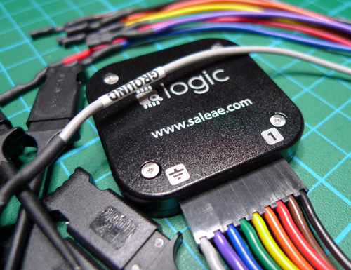
CAN Hacking: The Hardware

So far we have discussed the basics of CAN, in-vehicle networks, and protocols used over CAN. We’re going to wrap up with a discussion of CAN tools, and parts to build your own CAN hardware.

Wiring

Unfortunately, there’s no set standard for CAN connections. The most common connector for high-speed CAN is a DE-9, with CAN high on pin 7 and CAN low on pin 2. However cables will differ, and many are incompatible.

CAN needs to be terminated, preferably by a 120 ohm resistance on either end of the bus. In practice, you can stick a single 120 ohm resistor across the bus to deal with termination.

Tools

A good CAN tool will let you transmit and receive CAN messages, interpret live data using CAN databases, and talk CAN protocols. The tools with this feature set are proprietary and expensive, but some hacker friendly options exist.

GoodThopter

The GoodThopter12

Based on [Travis Goodspeed’s] GoodFET, the GoodThopter by [Q] uses the Microchip MCP2515 CAN to SPI controller to access the bus. The open hardware tool lets you send and receive messages using Python scripts.

CAN Bus Triple

CAN Bus Triple

The CAN Bus Triple device provides an interface to three CAN buses, and can be programmed in an environment similar to Arduino. The open source code provided lets you muck with the second generation Mazda 3. Unfortunately, the hardware does not appear to be open source.

Saleae Logic

Saleae Logic

It’s not open source, but the Saleae Logic is a very handy and cheap tool for looking at CAN buses. It can capture, decode, and display CAN traffic. This is most useful when you’re building your own CAN hardware.

DIY

The Parts

If you want to design your own hardware for CAN, you’ll need two things: a CAN controller, and a CAN transceiver.

The CAN controller generates and interprets CAN messages. There’s many microcontrollers on the market with built-in CAN controllers, such as the Atmel ATmega32M1, Freescale S08D, and the TI Tiva C Series. When using a built-in CAN controller, you’ll have to use an external oscillator, internal oscillators are not sufficiently accurate for high-speed CAN. If you want to add CAN to an existing microcontroller, the MCP2515 is an option. It’s a standalone CAN controller that communicates over SPI.

The transceiver translates signals from the controller to the bus, and from the bus to the transceiver. Different transceivers are needed for high-speed and low-speed CAN networks. The NXP TJA1050 works with high-speed buses, and the ON Semi NCV7356 works with low-speed, single wire buses.

Dev Boards

There’s a ton of development boards out there featuring microcontrollers with a CAN controller. The Arduino Due‘s SAM3 processor has a controller, but there’s no transceiver on the board. You can pick up a CAN bus shield, and the Due CAN Library to get started.

The ChipKIT Max32 is similar to the Due. It has two CAN controllers, but you’ll need to provide external transceivers to actually get on a bus. Fortunately there’s a shield for that. The ChipKIT is officially supported by Ford’s OpenXC Platform, so you can grab their firmware.

That concludes our discussion of CAN Hacking. Hopefully you’re now ready to go out and experiment with the protocol. If you have questions, send them along to our tip line with “CAN Hacking” in the subject, and we’ll compile some answers. If you liked this series and want to suggest a topic for the next set of posts we’d love to hear that as well!

CAN Hacking

Learn To Translate IR Codes And Retransmit Using Arduino

[Dave Jones] from EEVBlog.com takes “Arduino fan boys” off the garden path getting down and dirty with different methods to capture, evaluate and retransmit IR remote control codes. Capturing and reproducing IR remote control codes is nothing new, however, [Dave] carves his own roads and steers us around some “traps for young players” along the way.

[Dave] needed a countdown timer that could remotely start and stop recording on his Cannon video camera, which he did with simplicity in a previous EEVBlog post using a commercial learning remote control unit. The fans demanded better so he delivered with this excellent tutorial capturing IR codes on his oscilloscope from an IR decoder (yellow trace) as well as using an IR photo transistor (blue trace) which showed the code inclusive of 38 KHz carrier frequency. Either capture method could easily be used to examine the transmitted code. The second lesson learned from the captured waveforms was the type of code modulation being used. [Dave’s] remote transmitted NEC (Japanese) pulse length encoding — which can be assertaind by referencing the Infrared Remote Control Techniques (PDF). Knowing the encoding methodology it was trivial to manually translate the bits for later use in an Arduino transmitter sketch. We find it amazing how simple [Dave] makes the process seem, even choosing to write his own sketch to reproduce and transmit the IR codes and carrier instead of taking the easy road looking for existing libraries.

A real gem of knowledge in the video was when it didn’t work! We get to follow along as [Dave] stumbles before using a Saleae Logic analyzer to see that his transmitter was off frequency even though the math in his sketch seemed correct. Realizing the digital write routine was causing a slowdown he fudged his math to make the needed frequency correction. Sure, he could have removed the performance glitch by writing some custom port control but logic dictates using the fastest and simplest solution when hacking a one-off solution.

[Dave’s] video and links to source code after the break.

Continue reading “Learn To Translate IR Codes And Retransmit Using Arduino”

More Fun With Syma 107 Reverse Engineering

Syma Reverse Engineering

[Jim] used a logic analyzer to do some in depth analysis of the Syma 107G helicopter’s IR protocol. We’ve seen work to reverse engineer this protocol in the past, but [Jim] has improved upon it.

Instead of reading the IR output of the controller, [Jim] connected a Saleae Logic directly to the controller’s circuitry. This allowed him to get more accurate timing, which helped him find out some new things about the protocol. He used this to create a detailed explanation of the protocol.

One of the major findings is that the controller used a 3 byte control packet, which contradicts past reverse engineering of the device. There’s also a new explanation of how multiple channels work. This allows multiple helicopters to be flown without the controllers interfering.

The write up is quite detailed, and explains the reverse engineering process. It also provides great information for anyone wanting to hack one of these low cost helicopters. From the details [Jim] worked out, it would be fairly easy to implement the protocol on your own hardware.