Furbies Sing Queen At Fresher’s Faire

kent-furby

The University of Kent has their own hacker space, called  [Maker Society]. Every year the school holds an orientation for new students called the Fresher’s Faire. The [Maker Society] display at this year’s Fresher’s Faire included a group of partially clothed Furbies singing the classic Bohemian Rhapsody by Queen. This isn’t our first run in with Bohemian Rhapsody and hacked hardware.

The [Maker Society] started by doing some internet research and reverse engineering a first generation Furby.  The Furby itself is a marvel of cost reduction. All the doll’s functions run from a single motor and a cam system. A limit switch tells the on-board microcontroller when the cam is at the zero position. An optical encoder keeps track of the cam as it moves. The [Society] replaced Furby’s internal microcontroller with an Atmel ATMega328. This allowed them to use the Arduino programming environment.

Many classic Animatronic systems use an audio recording for motion. Typically a stereo recorder would perform double duty. The first track would contain the audio for the animation. A second track would contain audio tones corresponding to movement of each of the degrees of freedom of the doll being animated. Because the two tracks were on the same strip of magnetic tape, the audio and movement would always be in sync. Multitrack tape record and playback systems added even more flexibility to this type of system.

Continue reading “Furbies Sing Queen At Fresher’s Faire”

Finding Shiny Pokemon Automatically

In case you’re not up to speed with the world of Pokemon, nearly every species of this game’s titular creatures have a ‘shiny’ variety – a differently colored sprite for each pokemon. As far as gameplay goes, they’re exactly the same as their non-shiny brethren, but the shiny varieties are so impossibly rare not many players have seen them. [dekuNukem] over on Youtube has come up with a great way to find these shiny Pokemon automatically with the Hackaday reader’s favorite tools – an Arduino and a few parts from Sparkfun.

The build hinges on the fact that all shiny pokemon have a short animation whenever the player encounters them in the wild. This setup uses a fishing rod, so an Arduino Micro first presses the Y button to cast the rod, while the ‘duinos ADC listens to the audio signal until a bite is indicated.

A light sensor taped to the bottom screen of the 3DS then measures the amount of time the screen is blacked out. The extra animation for every shiny pokemon means this blackout period is about half a second longer. If the Arduino doesn’t see a shiny, it ‘runs away’, but if a shiny is detected a buzzer sounds to tell the extremely lazy pokemon trainer they have a shiny on their line.

From the video, it took about 36 minutes to find a single shiny pokemon, and about 8 shinies in the three hours of testing this rig has under its belt.

Continue reading “Finding Shiny Pokemon Automatically”

Retrotechtacular: World’s First Color Movie

world's-first-color-movie

It’s surprising how often a brilliant idea is missed out on until years after the fact. In this case the concept was seen publicly within ten years, but the brilliance of the inventor has been appreciated once again after 110 years. It’s a color movie which was filmed around 1901 or 1902 but it sounds like the reel wasn’t shown in its full color grandeur until 2012 when the National Media Museum in the UK started looking into the history of one particular film.

The story is well told by the curators in this video which is also embedded after the break. The reel has been in their collection for years. It’s black and white film that’s labeled as color. It just needed a clever and curious team to put three frames together with the help of color filters. It seems that [Edward Turner] patented a process in 1899 which used red, green, and blue filters to capture consecutive frames of film. The patent description helped researchers put image those frames — also using filters — to produce full color images like the one seen above.

The press release on the project shares a bit more information, like how they determined the age of the film using genealogical research and the fact that [Turner] himself died in 1904. The process didn’t die with him, but actual evolved and was exhibited publicly in 1909. This, however, is the oldest known color movie ever found.

Continue reading “Retrotechtacular: World’s First Color Movie”

CAN Hacking: The Hardware

So far we have discussed the basics of CAN, in-vehicle networks, and protocols used over CAN. We’re going to wrap up with a discussion of CAN tools, and parts to build your own CAN hardware.

Wiring

Unfortunately, there’s no set standard for CAN connections. The most common connector for high-speed CAN is a DE-9, with CAN high on pin 7 and CAN low on pin 2. However cables will differ, and many are incompatible.

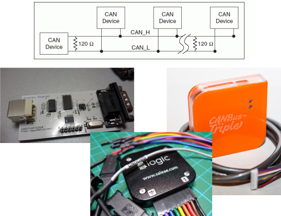
CAN needs to be terminated, preferably by a 120 ohm resistance on either end of the bus. In practice, you can stick a single 120 ohm resistor across the bus to deal with termination.

Tools

A good CAN tool will let you transmit and receive CAN messages, interpret live data using CAN databases, and talk CAN protocols. The tools with this feature set are proprietary and expensive, but some hacker friendly options exist.

GoodThopter

The GoodThopter12

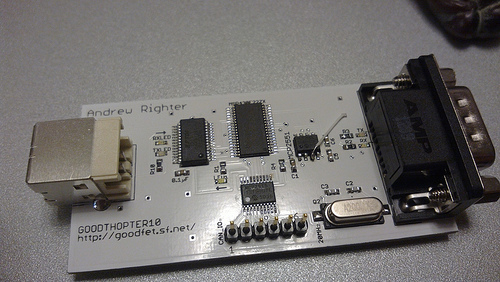
Based on [Travis Goodspeed’s] GoodFET, the GoodThopter by [Q] uses the Microchip MCP2515 CAN to SPI controller to access the bus. The open hardware tool lets you send and receive messages using Python scripts.

CAN Bus Triple

CAN Bus Triple

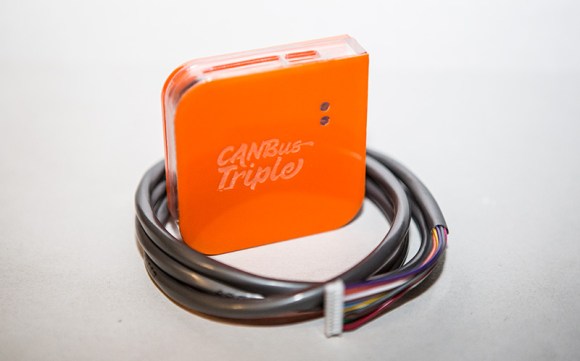
The CAN Bus Triple device provides an interface to three CAN buses, and can be programmed in an environment similar to Arduino. The open source code provided lets you muck with the second generation Mazda 3. Unfortunately, the hardware does not appear to be open source.

Saleae Logic

Saleae Logic

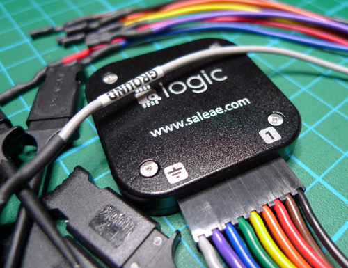
It’s not open source, but the Saleae Logic is a very handy and cheap tool for looking at CAN buses. It can capture, decode, and display CAN traffic. This is most useful when you’re building your own CAN hardware.

DIY

The Parts

If you want to design your own hardware for CAN, you’ll need two things: a CAN controller, and a CAN transceiver.

The CAN controller generates and interprets CAN messages. There’s many microcontrollers on the market with built-in CAN controllers, such as the Atmel ATmega32M1, Freescale S08D, and the TI Tiva C Series. When using a built-in CAN controller, you’ll have to use an external oscillator, internal oscillators are not sufficiently accurate for high-speed CAN. If you want to add CAN to an existing microcontroller, the MCP2515 is an option. It’s a standalone CAN controller that communicates over SPI.

The transceiver translates signals from the controller to the bus, and from the bus to the transceiver. Different transceivers are needed for high-speed and low-speed CAN networks. The NXP TJA1050 works with high-speed buses, and the ON Semi NCV7356 works with low-speed, single wire buses.

Dev Boards

There’s a ton of development boards out there featuring microcontrollers with a CAN controller. The Arduino Due‘s SAM3 processor has a controller, but there’s no transceiver on the board. You can pick up a CAN bus shield, and the Due CAN Library to get started.

The ChipKIT Max32 is similar to the Due. It has two CAN controllers, but you’ll need to provide external transceivers to actually get on a bus. Fortunately there’s a shield for that. The ChipKIT is officially supported by Ford’s OpenXC Platform, so you can grab their firmware.

That concludes our discussion of CAN Hacking. Hopefully you’re now ready to go out and experiment with the protocol. If you have questions, send them along to our tip line with “CAN Hacking” in the subject, and we’ll compile some answers. If you liked this series and want to suggest a topic for the next set of posts we’d love to hear that as well!

CAN Hacking

Fork-o-Drumbot: A MIDI Drummer!

forkotitle

We just got word of a great project by [Vito] — A MIDI Drumbot made from an Arduino and scraps from around the house!

After learning some basics of programming microcontrollers way back in high school, [Vito] was excited to start using the Arduino platform. His first thought was to build a desktop milling machine for engraving his own PCBs. But after a bit of research, he soon concluded it might be a bit too ambitious for a first project, so he opted for something a bit simpler — A robot drummer.

Using some cardboard, a few elastics, a plastic fork, a 12V solenoid, an Arduino and a MIDI interface he had created the original Fork-o-Drumbot, able to tap a simple beat, using one note. After this initial success he grew excited to continue along the same vein of recycling things to characterize his entire project. Fast forward a few weeks of blog posts and he now has a fully functional MIDI drummer which even has a cymbal! They were even featured in the local newspaper after performing a duet with a local singer during an art exhibit called the Singing Balconies of Friedrichshain.

Stick around after the break for an extremely catchy rendition of Superstitious by Stevie Wonder, as played by the Fork-o-Drumbot!

Continue reading “Fork-o-Drumbot: A MIDI Drummer!”

Can An 8 Node Raspberry Pi Cluster Web Server Survive Hackaday?

Plenty of folks have used their Raspberry Pi as a web server. [Steve] however is the first 8 node load balanced pi cluster server we’ve run into.  While we have seen pi clusters before, they’ve never been pressed into service as a public facing web server. [Steve] has created a really nice informative website about the Raspberry Pi, and Linux in general. As his page views have increased, he’s had to add nodes to the server. Currently [Steve] sees about 45,000 page views per month.

At first glance it would seem that the load balance system would be the weak link in the chain. However, [Steve] did realize that he needed more than an Pi to handle this task. He built the load balancer using an old PC with 512MB of RAM and a 2.7GHz x86 CPU. The most important thing about the balancer is dual network interfaces, one side facing the internet, the other facing the Pi cluster. The balancer isn’t a router though. Only HTTP requests are forwarded. The Pi nodes themselves live on their own sub net. Steve has run some basic testing with siege, however nothing beats a real world test. We figured a couple of links in from Hackaday would be enough to acid test the system.