Thermal imaging cameras – those really useful devices that give you Predator vision – are incredible tools. If you’re looking for heat escaping your house through a window, or just trying to figure out where your electronics project will explode next, they’re invaluable, if expensive, tools. [Kaptein QK] figured out an easy and cheap way to make your own thermal imaging camera using nothing just a few dollars worth of parts.
[Kaptein] based his camera off of a non-contact IR temperature gun. This device is useful for spot checking temperatures, but can’t produce an IR image like it’s $1000 cousins. By taking the thermopile out of this temperature gun, adding an op-amp, an A/D converter, and connecting it to an Arduino Nano with pan and tilt servos, [Kaptein] was able to slowly scan the thermopile over a scene and generate an image.
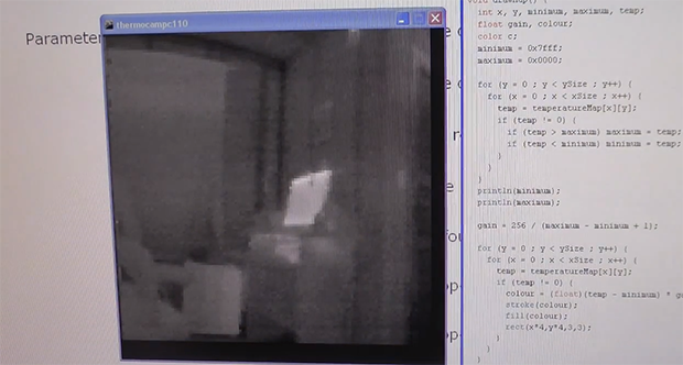
In the video below, you can see [Kaptein]’s scanning camera in action reading the ambient temperature and creating an imaging program for his PC. It works very well, and there a lot more [Kaptein] can improve on this system; getting rid of the servos and moving to mirrors would hopefully speed everything up, and replacing the 8-bit grayscale display with colors would give a vastly improved dynamic range.


Well, has been done before some times (f.e. http://publiclab.org/wiki/scanning-thermal-camera), but still nice.
But damn, I want an affordable real thermal camera :(
Check out muoptics.com. Shipping soon I hope. I really do like this scanning type IR sensor and hope to implement a thermostat that actually measures low thermal mass targets to determine room temperature instead of guessing and anticipating like present thermostats do.
lol, I thought that was vaporware :D their website is still quite low on details, but lets hope the best…
Muoptics will never ship. They have yet to show any evidence of an actual product or the competence to produce anything. Get a refund if you can & forget about them.
i want to believe :D
On their website you can preorder but they don’t want your money, you just get on a waiting list. Bad luck only for the indiegogo people who backed…
i was able to get my money back around a month ago.
Hi Mike, watching your most recent vids I would consider you an authority on thermal imaging within the hacker/mod community. In regards to Muoptics, is such a device actually feasible within the size and price they claim? (assuming one would know how to design and build one)
I don’t expect it to come from them, BUT, is it all just fairy tales or do you think it can actually be done?
I like this hack, and can see it being quite useful if you are measuring (viewing?) something that is a fairly stable temperature. I have often wondered whether investing a few hundred notes on a FLIR to track down the many draughts in my house would pay for itself in saved heating costs in, say a year or two? Perhaps this would make a good poor man’s ‘breeze finder’ instead?
Not at present – the sensor and optics just aren’t there yet. TIC prices are coming down slowly, and things like developments for the automotive safety market (sensor packaging and moulded chalcogenide glass optics like on the E4) will help but there are too few sensor manufacturers for serious competition and potential volumes aren’t there to get down to Mu’s price point with any serious resolution any time soon. Maybe in a few years.
Or you could look into renting an IR camera for a day or two to do your draft hunting.
(Much less cost to offset).
I would also be curious about the typical payback time on such an approach.
(For that matter, how hard is it to hack together a blower door test.)
Agreed. The McGraths (John and Charles) appear to be some kind of family duo who wanted to “do business together”. In my experience, mixing business with family/friends can be a nightmare…whether or not this was the case for them, they have been unable to deliver a product or updates. It sounds like they’ve been handing out refunds to the seekers, so I might see about getting mine so I can spoil myself over the holidays.
um, most thermostats include a “low thermal mass target”. If you’re worried about placement in the room, why not just slap together a thermocouple and a wireless module?
I graciously accept the “um” and cautiously respond with Well, most t-stats have a low mass sensor attached by wires (nice thermal conductors) to a large thermal mass (PCB) inside a large thermal mass (the case) with surprisingly poor airflow. Most t-stats I have tested have a time I constant of 12 to 20 minutes even when not attached to a heavy thermal mass known as a wall. S, unless you have very slow heating or cooling your tstat will havework very little idea of room t without a fan or other forced air device. A thermo sensor on 4 to 8 inches of thin wire 1 or more inches from the wall works great. Wireless sensors have a 5 to 12 minute time constant. Anticipation is mandatory for semi decent response but will always go wrong.
TL. DR. Use a fan, long wire free air sensors, or low mass IR targets or fudge the guess.
Sorry. Typing on mobile with time constraints and an edit window that kept running off screen and autocompleting. Arrrg.
Not sure if the long time constant (or hysteresis) you observed is by design.
Depending on the heater type, sometime you don’t want them to be switching
on/off every few seconds.
Well we had salesman in our company with Flir cameras. The cheapest camera cost around 1500 USD, which is not so much :) BUT it have very bad resolution and no focusing abilities…
Well there is a fix for the resolution and the focussing, google Flir E4 hack
thats still too much to hook it on a quadcopter like those guys did: http://www.youtube.com/watch?v=wqlptPhFmk0
but still a lot cheaper than the thermal camera we got at the fire department which cost some 20k (ok, with shock/heat/water proof case and stuff) 4 or 5 years ago
You can increase the dynamic range of the detector by showing the output in color? Holy crap…I’ve been doing it wrong for years!
Yeah. right now there are 256 values that can be displayed in black and white.
In fact, you can see this range adjustment happening in the video.
that was sarcasm silly. greyscale is still the best single-channel display method.
yea…color can enhance visual contrast (the distance between levels on the colormap is larger), but the dynamic range is the same. It only depends on the coldest spot in the image, the warmest spot in the image and the number of bits you have to span. If you want higher dynamic range, you will need to either get a higher bit-rate sensor, or super-window with multiple scans at different integration times.
” It only depends on the coldest spot in the image”
Not on professional cameras? They depend on pre-calibrated values don’t they?
@Eirinn No they have multiple modes and the most frequently used mode I’ve come across is autoscaling with a visual scale on the side showing the high and low colours thus: http://www.afestlouis.org/FLIR-Systems.jpg
@Matt No your display method can absolutely limit dynamic range. A typical TN film panel display processes colour in 6bit and severely bands when displaying a greyscale gradient. Depending on viewing angles as well you either experience black crush or white wash. So if you setup your 12bit Arduino ADC correctly (yeah right, but that’s a different story) to display the dynamic range properly you need to make use of more colour shades.
Its much cheaper than this one http://blog.arduino.cc/2012/10/25/diy-less-expensive-thermal-imaging-camera/ so that’s a big plus. Its very slow though. Looking at the code the 150×150 pixels image it takes almost 19 min to produce. That’s Victorian picture era slow! He may be able to reduce the delay(50) as the sensor only needs 25 msec per reading but it would still take about 10 min per image.
Do mirrors reflect IR light properly?
Front surface mirrors will work. I get IR reflections from bare metal all the time.
The real problem to speeding the scan up would be sensing element settling time.
e.g.
0.04 Seconds min (MLX90614xAx )
0.06 Seconds min (MLX90614xBx, MLX90614xCx)
These kind of times by 150 by 150 would give a scan time minimum of 15 minutes (or 22.5 for the slower ones). You could scan faster but then the sensor would not have enough time to reach steady state and the measured temperature in ° C would be off every time. But you could add some maths to compensate and extrapolate the approximate actual temperatures.
[A]-[B]-[C]-[….]
Ta Tb Tc
If point A was measured at temperature Ta and the next
point B was measured at temperature Tb and the next
point C was measured at temperature Tc
If Ta Tb then add a negative fudge to compensate. The fudge factor would need to be adjusted as the sampling time is varied. And all this assumes that the sensor is linear, which they never are :)
I hate that i can’t use less than and greater signs in posts. The above should have read
If Ta was greater than Tb then add a negative fudge to compensate (for the temperature going down). The fudge factor would need to be adjusted as the sampling time is varied. And all this assumes that the sensor is linear, which they never are :)
You can! < and >
That’s because WordPress tries to interpret you’re < and > as html tags. The way around that is html symbols such as:
< < less than
> > greater than
& & Ampersand
≤ ≤ less or equal
≥ ≥ greater of equal
And many many more:
http://www.w3schools.com/tags/ref_entities.asp
http://www.w3schools.com/tags/ref_symbols.asp
Also I went out and found a list of all the html tags that are supposed to work in WordPress comments. So I thought I’d try them all out here and see how they look.
<a href=”http://example.com” title=”tooltip text”>Link text</a>
Link text
<abbr title=”Abbreviated text”>Abbr Txt</abbr>
Abbr Txt
<acronym title=”Tool Tip Text”>TTT<acronym>
TTT
<b>Bold text</b>
Bold text
<blockquote>Indented text</blockquote>
<cite>Source information</cite>
Source information
<pre><code>for i in range(10):
print( “Code” )</code></pre>
<del>Deleted text</del>
Deleted text<em>Emphasized text</em>
Emphasized text
<i>Italicized text</i>
Italicized text
<q>Short quotation</q>
<strong>Bold again?</strong>
Bold again?
Of course if you take two sensors you can half the time, or double the resolution.
Rather than doing a compensation within software you could probably add a shutter in between the surface you are measuring and the sensor. By closing the shutter while the sensor is moving you can recalibrate it to a known temperature. Combined with a thermistor for ambient temp compensation you could have fairly acurate readings at decent speeds. The ZTP-135SR from GE has built in thermistor for this sort of compensation.
http://www.ge-mcs.com/download/temperature/920-159C-LR.pdf
Also, I saw below that someone said to add more sensors to speed up the process. This is true, but i’m sure a decently crafted lens made of the right material (geranium) combined with some FFT post processing could result in high resolution thermal images.
I have been really wanting to do something like this and use compressive sensing (http://en.wikipedia.org/wiki/Compressed_sensing) to help increase the resolution and speed of acquisition. One of these days…
If you’re dead set against servos, not sure how you’d move the mirrors. How expensive are good infra-red mirrors?
galvos
Polished copper serves as reasonably good infrared mirror
I have a RayTemp3 IR thermometer which upon investigation turns out to be a re-badged ZyTemp TN400L1, http://www.zytemp.com/products/tn400L1.asp
Inside the case is a small breakout board with 4 unused pinheaders (accessable by opening the battery cover) and holes for a K type thermocouple socket, but they didn’t add the socket, and the main board has extra pads for 3 more buttons below the screen. ‘Pressing’ the extra pads gains access to more functions of the thermometer that they didn’t intend the end user to access, backlight on/off, contious scan and other functions I haven’t figured out yet.
Also on the main board are some unused pinheader sockets labelled VCC, CD3, DCK, DIO, GND, as well unused pads, one set called Buzzer on one side and another called SPK on the other.
I’m really going to have to properly investigate it one day for this kind of imaging project..
First of all, why isn’t X axis servo movement smooth? This would greatly improve stability. Also, it wastes time returning to the left. (While this may introduce a slight misalignment of odd and even lines, it should be easy to account for in the software)
RC Servos are not know for their smoothness. They would probably be better off using steppers.
To reduce cost even further. They could use two galvos from old/broken hard disks for scanning. Placing the IR sensor where the laser would be in this setup.
https://www.youtube.com/watch?v=5zwjoRBYadE
I will not improve the scan speed (see my post above) but it would drop the cost.
Forgot to say, it’s probably the best image from a DIY thermal imaging setup I’ve seen which uses a single sensor and not an array.
Also, when they filmed Predator they did take a thermal imaging camera into the jungle but it was big, heavy and they didn’t get the desired footage they were after because it was so hot and humid, so they used normal film and did post-processing on it afterwards to make it look like a thermal image.
I can’t see the need for flyback in this system.
I suppose it might help a bit to keep the horizontal aligment, line by line. If that matters much. There’s the possibility of zig-zagging if it is a big deal, tho at such a low res, it might not show up.
Also, on that issue, means that if you were gonna have, say, a horizontal stop, you’d only need to put one on the left hand side.
Depends how much time it wastes, as to how much of a bother it is. The whole thing’s quite slow anyway. I like the idea others have had about using multiple sensors, even a small cheap array would be good. The right relationship between the pixel pitch of the sensor, and the amount it moves for each scan, could make a big difference to it’s speed and accuracy. Even if you could get it down to a few seconds, maybe 10, for a picture, it’d be practically useful for lots of things, specially if it came on a tripod.
I also wonder if there’d be any point attaching a Peltier cooler. I wonder is the calibration fixed or self-calbrating? And would a cooler affect that usefully?
A lot of comments here are talking about the inability to speed up the system due to problems with the servo, settling time, reading time, etc.
You could double the speed by adding a second sensor… just like a scanner. And like a scanner you can also get basic grid based thermopile sensors.
Or maybe three sensors, shades of Philo Fransworth, RIP.
interesting read. Thanks for the info :) Keep on tinkering :)
I knew someone was going to do this eventually!
Good stuff!
Nice. Built a similar thing with a Raspberry Pi and MLX90614 sensor, so the whole processing could be done on the RasPi. Makes a self contained/standalone/portable unit, UI via Browser/WiFi from a Smartphone. And it’s in color too!
Code is here:
https://github.com/hermann-kurz/thermography-raspberrypi
Explanation (in german) here:
http://www.μc.net/2013/07/thermographie-kamera-mit-dem-raspberry.html
sample image:
What’s with the URL not matching the one written down, and are you even allowed the Greek letter “mu” in a domain name? I thought it was 7-bit ASCII, presumably also-known-as ANSI or ISO standard something-or-other. Actually ISO would be less confusing, there’s already a standard for ANSI text that’s a bit different, almost the opposite.
Are they bothering with Unicode in domain names any time soon? Not really the place to ask, I’m just curious. If anyone wants to send me to a good web site that gets to the point quick, I’d be happy.
It is called IDN, see http://en.wikipedia.org/wiki/Internationalized_domain_name, this is about 10 years going on. And yes, if you type “µc.net” into your Browser, you are actually taken to http://xn--c-lmb.net/. Some browsers (ie Chrome) will display the decoded IDN, others the original URL (Firefox).
Just a random question, would green not be a better color than gray, considering that it is supposedly the most easily spotted, as far as variation and intensity are concerned (supposedly also why night vision goggles use green?)
I wonder if it’s possible to accomplish the raster scanning effect using a DMD chip. It seems like everyone is throwing their DLP televisions away, so it wouldn’t be difficult to obtain on a budget. I’m just not sure if a standard DLP lens would allow the appropriate spectrum of infrared to pass through it.