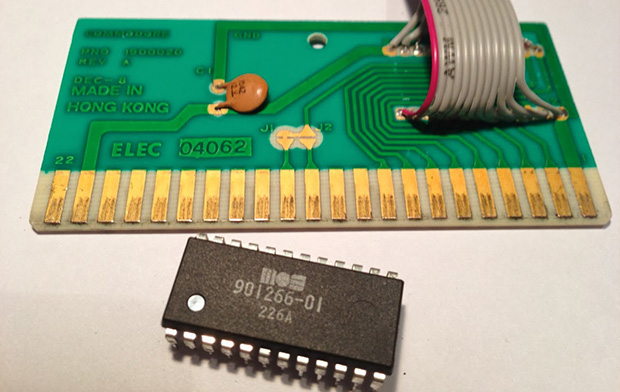
[Petri]’s first computer was the venerable Commodore VIC-20, predecessor to the Commodore 64. With only 5kB of RAM, a very simple graphics chip, and BASIC, it’s a bare-bones system that’s perfect for a 7-year-old future programmer. [Petri] was trying to figure out something to do with this old computer, and realized the simple schematic would allow him to recreate those classic VIC-20 cartridges using modern hardware.
This project began by cracking open a few game cartridges to see what was inside. They’re very simple devices, consisting of a decoupling cap and a ROM chip wired directly to the data and address busses. [Petri] desoldered the ROM and replaced it with a ribbon cable that would give him a clean breadboard to VIC-20 expansion port interface.
Instead of finding a contemporary EEPROM chip to program, [Petri] decided on using a Flash chip. The original cartridge had a 16kB ROM chip, but the smallest parallel Flash chip he could find was 256k. No problem, then; just ignore a few address lines and everything worked out great.
After getting the VIC-20 reading the breadboarded Flash chip, [Petri] started work on a circuit that would program his Flash chip while still attached to the expansion port. With a few buffer chips and an ATMega32a loaded up with Arduino, he’s able to program the Flash chip and turn it over to the VIC-20.
A simple test that toggled the color of the screen as quickly as possible was all that was needed to test the new circuit. Now, [Petri] can finally start on programming some games for his first love.


This is cool.
Quick suggetion, the original ROMs were 8k*8, and the Flash is 256k*8, according to the linked site. So how about adding switches to the five additional address lines, and having 32 different ROM images in the one Flash?
Ooooh, very clever if it works!
I do like this idea very much!
Yep, I’m planning to utilize the extra space in the final version. I’ll probably include a button for toggling the banks and let the ATmega control those additional address lines. I’m also thinking about adding some extra RAM on board but it’s going to be a tight fit because I would like to built the whole thing inside the original game cartridge enclosure. Stay tuned for part 2/2 :)
Rather than using a microcontroller, use a hexadecimal switch!
http://google.com/images?q=hexadecimal+switch
Maybe not, they’re disproportionately expensive. I like the way they look, though.
Maybe use one of the reset-based detectors. Or add a menu and a latch.
Good idea! I like the low tech approach :) I happen to have a few hex-encoders here. I got them $1 a piece.
We used to do that back in the day. there were a lot of “bootleg” rom cars around and you could buy multiple rom cartridges, you flipped the dip switch and then plugged it in.
For the address lines, ignore as in floating or ignore as in pulled low?
Yeah, unused address lines need to be pulled low otherwise reads will go randomly all over the memory.
To echo the first commenter, this is *very* cool.
This might be the ticket to fixing-up my ol’ Tek 7854 ‘scope using new parts, with the added benefit of playing with the firmware on-the-fly (for no reason other than ‘why not’).
If you get a little more complicated and use a register for the additional address lines (mapped to some memory location) you could switch out the ROM images in software and even have menus for the contents of the flash.
Using an extender board, I used to do this with static RAM that I’d load the program into using the BASIC interface and floppy drive, then do a soft reset to start execution of the what was stored in RAM.
The Vic 20 was the first computer I used for accessing BBS via an acoustic coupler. Terminal program was on cassette tape… LOL those were the days! Super project :)
I bet that was awesome! Modems never took off in the UK, for the first few years I was on the Internet we had to pay by the minute for the phone call.
Didn’t the VIC-20 only have 3.5k RAM?
An unexpanded VIC-20 has 5kB of RAM of which 3.5kB can be used for BASIC programs.
Could you please tell me the J2 trace on the cartridge board connected to which pin of the original 8K ROM chip? Thanks!