[Tyson’s] family went with creating rather than buying Christmas presents last month, which gave him the opportunity to build some electronic fireflies for gifts. He drew inspiration from a similar firefly project we featured last year, but expanded on the original model by designing dedicated PCBs and housings for each of his firefly pieces.
Although he’d settled on using ATTiny85’s for this project, [Tyson] was fresh out of through-hole versions. He decided to skip the prototyping phase and go right for fabrication, cranking up the laser-jet printer for some toner-transfer, which successfully produced 4 functioning boards (and 3 failures). The fireflies were [Tyson’s] first attempt at SMD soldering, and we’d have to say it’s a job well done; he reflowed each board with a cheap-o heatgun from Harbor Freight.
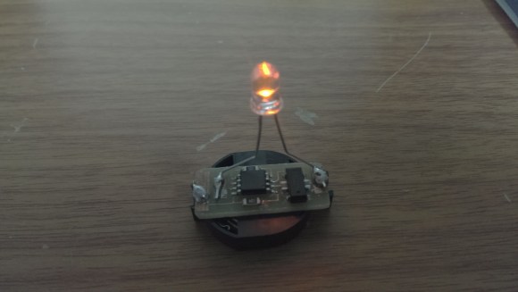
After some hiccups with fuse programming, [Tyson] got the code uploaded and the fireflies illuminated. Swing by his site for the nuts and bolts on construction, then snag the project files here. (Direct .zip download)


Good newbie project. I haven’t done any SMD soldering yet either, but I think it would have helped to prevent solder bridging by putting flux on the board before adding solder pads. I’m surprised he has 30+ days of LED illumination on a 3v CR2032 powering the ATTiny85 — I’ve recently had problems with 9v batteries on a 5v regulator lasting less than a week with a similar setup, but I’ve also been using multiple LEDs that also seem to draw more mA per hour than this project…so I’m now using a bridge rectifier >> softener cap >> volt. regulator >> more caps >> ATTiny85 setup using the 15v AC line that powers my old doorbell as a more permanent power source.
Pretty neat, Tyson. Thanks for sharing!
I have a similar thing using a CR2032 and a tiny48 that drives 24 white LEDs, it runs for something like 24 hours, so i have no problem believing you could have one LED running for a month.
I built a tiny85-based firefly jar with six charlieplexed LEDs that’s been running since last May on a CR2450 (slightly bigger battery, but still…). It flashes a sequence of LEDs every few minutes. It also has a mercury switch, in it so you can shake the jar and make them ‘angry’. They flash more often for a while when you do that.
I was also pretty surprised to get so much life out of them. Although, the LED is on very little time, it only blinks every once in a while, and when it does it pulses with about ~9% duty cycle. From the datasheet, I imagine the idle current draw is somewhere between 50 and 100 uA, so it shouldn’t use too much power.
Last I checked, they’re still running strong on the original batteries. How long they’ll actually last, I have no idea.
As for the 9v to 5v regulator. I’d suspect you may have been dissipating a lot of power in the regulator itself. A typical 7805 might use a constant 5 mA or more even when idle.
That seems to be where my problem is: I’m using an LM317 adjustable volt. regulator and power dissipation seems to be the issue. I think I’ll go order some 7805s and see if that helps reduce the load.
A 7805 will still have a quiescent current in the mA range, and may not provide much benefit over the LM317.
You might look at different regulators to get a better quiescent current. Like the MCP1702, uses 2 uA quiescent current (less than 0.1% of the 7805 current), but it won’t source as much current as the 7805, maybe ~250 mA. If you need more current for other components, you might place them in line with a transistor and current limit them from the 9v.
Full disclosure: I’ve never used an MCP1702, but it looks like a good candidate for lower power devices.
@Tyson – you might want to crack open that heatgun and find some 10+ Amp recitfier diodes. they just use a 3A diode and it can explosively fail short during use, leaving you without a low setting
Thanks for the tip @Hyratel. It is a cheap HF heat-gun, so this does not surprise me. Good to know there’s an easy remedy!
To me, the hack in this is the super-bodgy way he went about making the PCBs. Out with all established ‘best practice’, and in with the ‘what do I have to hand’. Good show.
but why bother with the external oscillator? there’s an internal 128K one as well that can further be decreased..