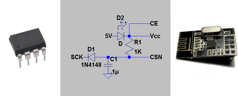
[Ralph] wasn’t satisfied with the required 5 control pins to drive his nrf24l01+ transceiver module, so he used this circuit needing just 3 pin using an ATtiny85.
One of the key components was to effectively drive the chip select (CSN) line from the clock (SCK) line. The nrf24l01+ needs the CSN line to transition from high to low on the beginning of a communication. [Ralph] put the SCK line behind a diode, put a capacitor in parallel with the CSN line and altered the arduino-nrf24l01 library to encode extra delays for the clock line. This allowed the CSN line to be driven by the SCK line. Subsequent line transitions during transmission happen too fast to charge the capacitor, leaving the CSN line in a low state.
After tying the chip enable line high and dropping the 5V power line to 1.9-3.6V across a red LED, [Ralph] had an ATtiny85 controlling a nrf24l01+ module.
Though deceptively simple, a very cool hack that opens up a couple more lines on the ATtiny85.


awesome, i need to try this. the number of pins this module eats up is rather large. amount of io even on a atmega328p. which has affected a few od my projects.
Be careful about using a red LED as a in-line voltage regulator; if you switch to the lowest power mode (datasheet says typical 900nA) of the nRF it will exceed the maximum permitted supply voltage. (Testing: a random red LED and a 1MΩ resistor resulted in 3.4V (3.4µA through) across the resistor/IC and my multimeter isn’t trustworthy with a 10MΩ resistor (it shows 4.8V across the resistor but 1V across the LED) … but either way, that exceeds the 3.6V permitted)
The datasheet also doesn’t mention a PSRR, so I’m also not confident that the IC won’t have problems with its Vcc varying widely as a function of power consumption.
Whenever I use an LED/other diode to “regulate” the voltage, I just pull a couple of mA through the diode with a resistor to ground to prevent the sort of thing you mentioned. Is that actually a good enough solution or have I just been lucky?
Even the 30µA the datasheet specifies in “Standby I” is enough to keep the LED forward voltage in an acceptable range. It’s just when you get down to <1µA that the forward voltage will almost certainly drop below 1.4V.
The currents are so low that it’s not an issue. For static discharge HMB currents it’s rated up to 1kV, and for MM up to 200V (datasheet pg. 3).
I am really skeptical that a persistent 5V, even if current limited to 1µA, won’t have a deleterious effect. It’s not enough to point at the static resistance, because that’s measured in terms of a total amount of charge injected across the device, not a constant low current.
To avoid that possibility, then James’ suggestion would provide some insurance. A 100k should keep the diode in the >1.5Vf range. Depending on the diode, you might even be able to see a faint bit of light from it.
Now you can put some NFC tags on your toilet seat and drive it with ATtiny, HELL YEAH SCIENCE!
I came up with a different solution a few years ago… though I must state up front that I haven’t tested it yet, only simulated using some online tools, as I put the project aside due to other things. It’s here.
My proposed solution holds SCK high, and uses a passive low-pass filter to keep the CSN line high in between transfers, and during transfers (so long as they’re not a lot longer than 32 bits).
Whoops, bad form to reply to my own post, but looking at my old write-up my scheme multiplexes SCK and CE, rather than SCK and CSN.
Are there two different versions of these? Some of mine won’t transmit but will receive, and vice versa.
I’ve heard there are siLabs clones of the nrf chip that work slightly different (lower default tx power I think). All mine seem to be the genuine nrf parts.
Hi, nice trick!! But I’ve a question related to CE pin that in my opinion it’s not clear or I didn’t understand.
When tying CE pin up or low, does it result in making the device work exclusively as transmitter or receiver?
Nerdralph’s example cannot be used as a transmitter.
Hello, is there a way in the middle to avoid problems? Like using just 4 pins? In my project two are occupied, so it would be just perfect.