

Last week we started to Make a Thing in Solidworks. We got as far as sketching and extruding the base. This week we’ll make the back portion. We’ll use some of the same techniques in Part I and a few new features such as 3D filleting and the Hole Wizard.
As you know, this is not the first ‘Making a Thing’ tutorial. In case you missed them, the softwares previously covered in the 3D Printering series are:
- OpenSCAD
- AutoCAD Part I
- AutoCAD Part II
- Blender Part I
- Blender Part II
- SketchUp
- Autodesk 123D
- FreeCAD Part I
- FreeCAD Part II
- Solidworks Part I
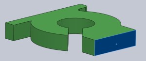
Picking up where we left off, the next step is to make the back portion of the shape. To do this, start by rotating the view to see the rear face of the part. We want our sketch to be on the rear face so select the rear face by clicking on it. Once it is highlighted, select Sketch from the Sketch Tab.
Sketch
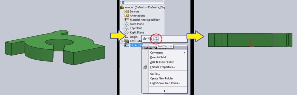
A new line will show up in the Model Tree (in this case it is called Sketch2). Right click on this and click on the Normal To icon. This will rotate the view to be perpendicular to the face the sketch will be on.
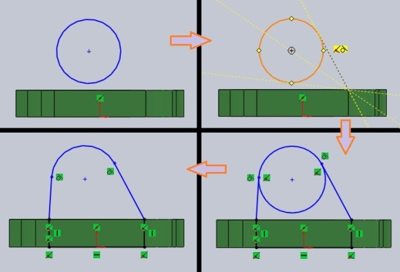
Now that we are looking at the rear face of the part, we can draw the back portion, which is basically a tombstone shape with tapered sides. Start by drawing a circle. It can be any size and any location as it will be dimensioned later. Like in Part 1, I will intentionally sketch the shape out of proportion to show how the geometry will change when adding dimensions and constraints.
The tapered lines should be tangent to circle. To do this, select the Line Tool from the Sketch Tab, start the line on one of the top corners of the rear face. Then hover over the circle near the point where the line would be tangent to the circle. A yellow box with a tangent symbol will appear. Clicking at this time will make the line tangent to the circle. Do this for the other side. Then draw the last 3 lines. Hovering over the corners of the rear face will make the lines snap to those points. On the Sketch Tab, select the Trim Tool and click on the bottom portion of the circle to delete it.
Dimension
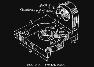
From the sample drawing, we know that the center of the arc is 7/8″ above the top face of the portion we have already drawn and extruded. Use the Smart Dimension Tool to add a dimension from the center of the arc to the top face of the extruded part. Then enter “7/8” as the desired distance and the sketch will move to satisfy that requirement. Click on the arc to specify its radius. Enter 5/8 or 0.625.
The radius is currently not centered over the rear face. To center it, left click on the top of the rear face and select the midpoint. Then hold shift and select the center of the arc. A window will pop up, select the vertical line to make the arc centered over the rear face.
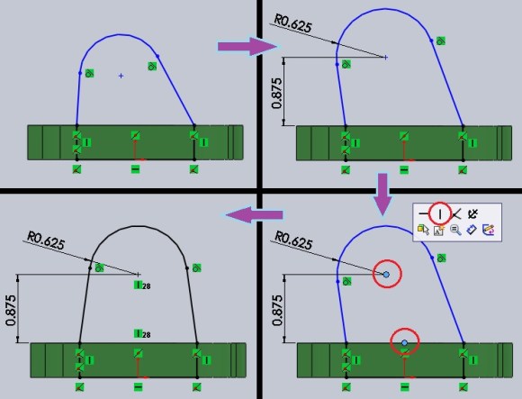
The sketch is now complete. Click Exit Sketch from the Sketch Tab.
NOTE: The 7/16″ through-hole could have been drawn on the sketch and it would have created a hole when the sketch was extruded. After that, the counterbore would still have to be added. We will create both the hole and counterbore in one step later.
Extrude
To extrude the part, select the sketch (Sketch2) on the Model Tree, then on the Features Tab, select Extruded Boss. In the Boss-Extrude dialog box, type in 0.5 or 1/2 to specify the length to extrude. Click the green check mark to make it happen.
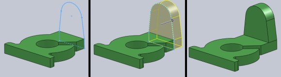
Hole Wizard
To make the hole and counterbore we’ll try something new. Select the Hole Wizard from the Features Tab. This tool will allow us to make the hole and counterbore at the same time. In the Hole Specifications Dialog Box, select the following:
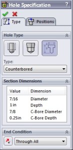 Hole Type: Legacy Hole
Type: Counterbored (adds a counterbore)
End Condition: Through All (makes the hole go through the entire part)
Enter the dimensions from the sample drawing for the Hole Diameter, Counterbore Diameter and Counterbore Depth.
NOTE: We can’t change the hole Depth because we specified “Through All” for the End Condition. If we selected “Blind” and added a depth of 2 inches, the hole would go into the part 2 inches deep.
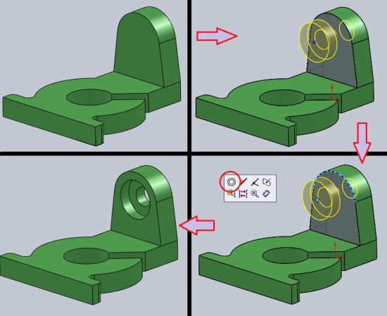
Now that the hole and counterbore dimensions are specified, we need to determine where the hole will be. While still in the Hole Specifications dialog box, click on the Positions Tab. Then select the face of the part where the hole will be placed. Position does not mater right now.
A representation of the counterbored hole will be placed on the part. We know it is not in the correct spot. To make the hole concentric with the arc of the back portion of the part, click on the asterisk at the center of the previewed hole, then hold shift and click on the arc of the part. A little window will pop up. Clicking on the icon made of two circles will make the two selected features concentric with one another. Hit the green check mark to finish the operation.
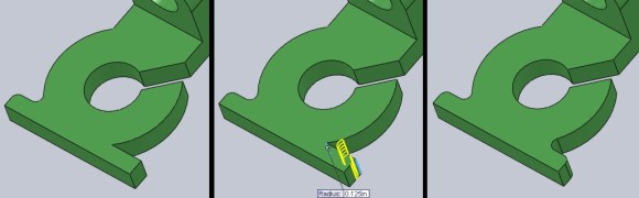
Fillet
Remember in Part 1, we left a couple fillets off of the drawing so that we could add them later. On the Features Tab, there is a Fillet Tool. Selecting this will open a dialog box where you can enter the desired radius of the fillet. The sample drawing stated these fillets were 1/8 inch. Enter that and click on the corners that need to be radiused. Solidworks will show a preview of the fillets. Click the green check mark to accept the preview.
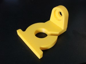
That’s it! Here’s the final product:

This Hackaday Column is called 3D Printering and in order to print the part, the file must be saved in .stl format. This is as easy as File-Save As. Select .stl from the file type list.
That concludes the Solidworks ‘Making A Thing’ tutorial. Happy modeling and printing!
3D Printering is a weekly column that digs deep into all things related to 3D Printing. If you have questions or ideas for future installments please sending us your thoughts.


This is too complicated, Blender and other open-source programs are superior to this bloatware.
Never before have I seen someone suggest Blender because they thought something ELSE was too complicated!
Also, Blender is really not appropriate for solids modeling like this. Although it’s certainly possible, Blender is mesh-based, and is best used for aesthetic rather than mechanical work. If you suggested to an engineer that they would be better off using Blender than Solidworks, they’d laugh up a lung.
If you’re not an engineer, and you’re doing this as a hobby, then what was wrong with SketchUp?
Nah, it is not too complicated, but SW is something you should stay very far away from. These scumbags offer their malware for free to schools in order to get students hooked on their drug and flood the market with cheap Solid Worker drones. Empoyers are charged one to two months salaries per worker drone.
As a student, you’d better invest your time elsewhere! As a maker, don’t even bother, it is not worth the trouble even to download an illegal copy of this crap.
If you’re a student in the fields of design, engineering, or anything related, you’ll want to know Solidworks like the back of your hand if you want any chance at getting a job within the field.
I am an engineering student and could not agree less with Sting and Jiog. As David said, if you want a job, you need to learn it. If you are a Maker, Solidworks is way over kill (and Blender is not the right tool for this either).
People don’t realize, Solidworks is a full engineering suite that offers VERY powerful tools like stress analysis, thermal simulations, down to just simple part listing and animation. It isn’t meant for the average home user. It is like using integral calculus to find the area of a square or triangle.
Yes, it is ~$8000, a little slow, not very intuitive, and I do find it infuriating at times but there are entire college courses dedicated to learning this software where as sketchup can be learned with a few youtube tutorials and is good ’nuff for the average guy.
perhaps it offers very powerful tools, but who actually needs them?
That very high price pays for the marketing and profits of Dassault. Very little of it goes toward support or software development.
Jelle – a good proportion of professional mechanical engineers and product designers use parametric solid modelling software. Me included. That’s who.
What do you know about their costs or level of support or software development?
That is a good way to point out that SW cornered a large part of the market and is hurting both employers and employees: If it is absolutely necessary for the field, then the price of that software goes through the roof: money that could have been better margins for the employer and/or better pay for the employee.
I’d love to see lower cost solid modelling CAD programs, but you have to know a bit of history before you can make any reasonable comments. Many of the original programs were developed for internal use in automotive and aerospace companies like Ford and EADS. As corporate structures changed, they started offering their software for sale to other enginerring companies. In the mid to late 90s high end modellers like Unigraphics, I-DEAS, Pro/Engineer and Catia might have cost over $100,000 per seat. Plus you’ve need to by a $50,000 Sun or Silicon Graphics Workstation to run it on.
Then mid-range modellers came along that would run on Windows. SolidWorks, Solid Edge and more recently Inventor. The price of Pro/Engineer was brought down to compete with mid-range modellers. Unigraphics and I-DEAS merged to become Siemens NX. Pro/Engineer is now called Creo. There are tons of others on the market too: solidThinking, Ashlar Vellum…etc.
So, SolidWorks has plenty of competition. It is not way better than any of the others, and the pricing is coming down. There are also a number of indicators that this will continue to happen:
1) There are a few reasonably decent free modellers around now: http://www.ptc.com/products/creo-elements-direct/modeling-express
http://www.powershape-e.com
http://www.softpedia.com/get/Multimedia/Graphic/Graphic-Editors/Alibre-Design-Xpress.shtml
2) There are a few reasonably decent low(er) cost modellers around now: http://www.autodesk.com/products/inventor-lt-family/buy $1,200
http://cubify.com/products/3d_design_software/compare.aspx
http://www.alibre.com/products/compareintnl.asp
3) Pro quality 2D CAD (as good as AutoCAD) is now free: http://www.3ds.com/products-services/draftsight/overview/
3) There is competition in the guise of low(er) cost subscription models: http://fusion360.autodesk.com/about
So, it’s not absolutely necessary – ever – to pay thousands of dollars/pounds/whatevers for a seat of SolidWorks.
Solidworks is my preferred modeler. I’ve tried Blender various times over the years for different reasons and never took to it. For 3d modeling parametric parts, Solidworks is perfect.
In the Blender Make A Thing, the author noted “Once again, I need to reiterate that Blender was the wrong tool for this job.”
What is complicated about it? You want a solid part? Draw the shape in a sketch and extrude it. You want a hole in that? Click the surface you want the hole on, create and position the hole in the hole wizard, and you’re done. I fail to see what is complicated about it…
I agree. It’s quite the reverse once you’ve had a couple of hours with any solid modelling package it’s very quick and easy to make robust (model wise), dimensionally accurate and easily editable models. Mesh modellers – while great for abstract and freeform artwork – are a nightmare in comparison for this kind of work.
yes, until you make something more trivial that this or your example and wish to change or remove something from the design tree. Good luck finding and fixing where something went wrong.
Every CAD tool is simple for simple shapes.
Removing something from the design tree is simple if you’ve constructed your model properly. If you’re using something like Solid Edge, it’s even easier with their synchronous technology. It’s much more difficult to do remove features cleanly on non-history based mesh or surface modellers. That and they’re next-to-useless for designing anything mechanical.
Both parts of the write-up are great, but I loved the “no nonsense” video from the first one; where’s the sequel?
So you’re saying Rich should do Solidworks tutorials?
No, I wasn’t asking about more tutorials, just the conclusion of the first video. I don’t, personally, need any more SW tutorials, since I don’t own it. Although, reading the first part (and watching the video) did help me wrap my head around the parametric modeling work-flow, which also applies to SolveSpace. After I read/watched part 1, I tried out the techniques in SolveSpace, and it made much more sense. As a result, I fully intend to start using SS a great deal, from now on.
Basically, I’m saying I liked the way he did the last video, and I want to see more like that. Not necessarily by Rich, nor necessarily about SolidWorks.
yes. definitely.
What no Pro/E Creo tut?
Pro/E is pretty much the industry standard… surprised to see SW before it.
Depends which specific industry. Not in a lot of areas of product design, it’s not…
Omg i would love to have solidworks. my previous jobs had this software and i had to create a PCBs and housing at the same time. Solidworks is by far superior to anything on the market… wish i could own a copy myself to go with my ROBO 3D. if you guys wont be using it ill be glad to take it off your hands. :)
One trip to the high seas of ye’ olde interwebs will not disappoint—argh shimber me timbers!
My work PC has SolidWorks installed and I like using it. I had to use it to make some 3D models for some ICs on my board. I wouldn’t buy it for home use, obviously, but if it’s there, I’ll use it. Thanks much for these guides, they seem like they will be helpful.
Anybody knows a trick to import STL files to SW parts?¿
Get a newer version of SolidWorks (2012 onwards, I think)….is the only way I know of.
Sorry, I dont talk clear. I know that SW imports STL files, but its a unique solid and you cant manipulate sketchs.
If i want to edit a piece of that only I have the STL file, I have to open with sketchup, take sizes and create a new 3d piece. Its a hard work, but i dont find another method.
(Sorry for my bad english)
An STL file is only a polygon mesh. No other information is stored in the file. So, it will never be possible to edit sketches or geometry like cylinder sizes, or thickness of a prism. The file is just a collection of points and triangles.
To be able to edit files properly you have two options:
1) Use the same solid modelling software, and use the native file format.
2) Use only solid modelling software that has “feature recognition”, and either use the native file format, or a neutral one like IGES or STEP.
I hope that helps.
I doubt it’s possible at all. STL doesn’t save the features, just the final shape, so SW would have to somehow reconstruct the geometry from the STL file.
I’m not sure if this needs extra options or not.
Open STL in solidworks.
Run import diagnostics to make sure the model is a complete skin.
Run Featureworks feature recognition. Automatic, manually, or a combination of both.
How well it works depends a LOT on how good the model was to begin with, and if the software created any rounding errors ect. when exporting to STL. Many times it will only recognize certain features and you will still have a remnant “imported solid” but also a lot of features you can work with natively.
Another approach is to use the STL as a referance, and make new sketches to recreate the model from. Hide the original imported solid. Then use the sketches to extrude/cut ect. a new native solid.
How about building this thing in your browswer at Tinkercad.com?
It comes down to whatever works for you. I have used most of the programs including Proe and Tinkercad. Since I started on Autocad 20 years ago I am probably most efficient on Acad software. If you have to spend most of your time thinking of how to use the program the design will suffer. If you have no aptitude for design the program will not design for you. I have seen a very economical bracket turned into part that could not be produced. If you don’t know how the machine works that makes the part you should not design.