We have posted articles in the past on directional antennas such as Yagi antennas used for transmitter hunting otherwise known as fox hunting. Those types of antennas and reception suffer from one major drawback, which is as you get close to the transmitter the S meter will go full scale. At which time the transmitted signal appears to be coming from all directions. To correct for this problem you need to use clever signal attenuators or change to a poor receiving antenna as well as tuning off frequency effectively making your receiver hard of hearing so that only the direct path to the transmitter is loudest.
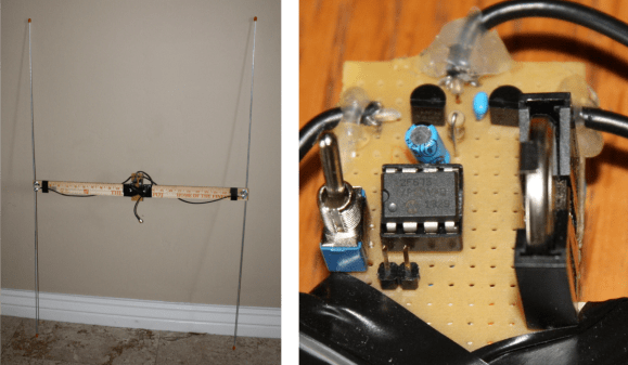
There is another popular type of antenna that you can build yourself called a TDOA which stands for Time Difference of Arrival. [Byon Garrabrant N6BG] shared a short video tutorial on the functionality of his home built TDOA antenna. Effectively this is an active antenna that uses a 555 chip or, in [Byon’s] case, a PIC chip to quickly shift between two receiving dipole antennas at either end of a shortened yardstick. In his explanation you learn that as the antenna ends move closer or farther from the source a 640 Hz generated audio tone will go from loud to very soft as the antennas become equal distance from the source. This type of directional reception is not affected by signal strength. This means you can be very close to a powerful transmitter and it will still function as a good directional antenna.
The current circuit diagram, BOM and source code are all available on [Byon’s] TDOA page.
The reason [Byon] used a programmable PIC instead of the 555 for his design is because he wants to add a few more modifications such as feeding back the audio output to the PIC in order to programmatically turn on a left or right LED indicating the direction of the transmitter. Furthermore, he plans on adding a third antenna in a triangular configuration to programmatically control a circle of 6 LEDs indicating the exact direction of the signal. When he finishes the final modifications he can drive around with the antenna array on his vehicle and the circle of LEDs inside indicating the exact direction to navigate.
We look forward to seeing the rest of the development which might even become a kit someday. You can watch [Byon’s] TDOA video after the break.


very nice and interesting build, would love to see the improvements once they are finished.
Instead of switching, could you also use 2 receivers, and mix the output tone ?
Yes if you really want to make it a whole lot more complex and massively more expensive. you will need at least 80X more parts to do it that way.
It’s not more expensive if you already have two receivers. But I wasn’t interested in parts count. I was just curious if it would work. And thinking about it some more, I don’t think it will.
I think it would work, but as I imagine it you’d have 4 possible directions the source could be, rather than the two that this build has.
I think you’d have a problem the mixer oscillators would not be sync, so each receiver adds a different amount of phase shift.
I think this tree is just explaining benefits of active vs. passive phased array receiver. DIY phased array! sounds so sweet.
Thats the way the origianl worked, 4 receviers all feeding a CRT, you can do the same thing with an oscope that has X-Y. the resulting scope plot, or its shape, tells you the direction of the signal. of course it woulf be more complex than I just explained, but they did it in the 1930-40s, so…
This article had me doing a lot of research on this, because others have problem with it being called TDOA. From what I’m reading multiple receivers could be employed, but they have to be carefully matched My guess is you wouldn’t get by with pulling receivers off the shelf and using them as they come out of the box, then again you might.
I remember building 20 years ago a similar circuit from Bob Leskovec, K8DTS, published in QST May 1993 called Handi Finder.
Now found that it’s a very popular kit. http://www.handi-finder.com/images/hfbook03a.htm
I have one built on perfboard laying with brass butterfly shaped antenna laying around somewhere….
Unfortunatly not available in europe… Lets see if I get at some point more time to get dirty with etching and layout.
There was a version of that that used a meter movement to identify left and right direction.
Watson-Watt
looks like it would come in handy for the RC plane people who on occasion lose a plane in the woods surrounding their RC club
Usually, the plane dosn’t transmit.
I was thinking you would include one of their transmitters in the plane, they seem small enough not to cause balance issues
Back in 2009 I saw many planes experience 2.4 lockout and go flying off into the woods surrounding the airstrip, was amazing how far away some of them flew before crashing into a tree somewhere
The explanation of how (or why) it works is spectacularly underwhelming.
The simple explanation is the circuit switches between the two antennas at an audio frequency. The result at the coax is a phase modulated signal, the phase shift depending on the distance between the antennas and the angle of arrival. The phase modulated signal is fed to an FM receiver, which produces a tone at the switching frequency.
Maximum audio level is produced when the two antennas are in line with the direction to the transmitter (maximum phase difference). Minimum (or zero) audio level is produced when the line of the two antennas is perpendicular to the direction to the transmitter (minimum phase difference). Minimum signal level is typically used to determine direction because the null is so much sharper.
I think most people that are commenting know how it works but there should be an explanation in your page and for sure, the comments is not the right place for that explanation.
Looks like there’s more to Byon than APRS – Nice work Byon.
I don’t think this is really TDOA. TDOA involves receivers at multiple sites and solving an equation of hyperbolas to find a location. This is more like phase interferometry or pseudo doppler (the switching between antennas causing an audible tone). Normally pseudo doppler is done with more antennas arranged in a circle. At any rate, this is definitely an interesting approach!
It’s a mordern version of a Watson-Watt DF receiver, initially designed by Sir R.A. Watson-Watt (aka “the father of radar”) in the 1920’s. It would be refered to as DOA DF, DOA being direction of angle. It doesn’t calculate time of flight or time of arrival of the RF energy to the dipoples… that would only work if the signal was pulsed and it knew when the signal was sent.
He got pulled over for speeding by a cop running radar in the 1960’s and wrote this poem afterwards:
Pity Sir Robert Watson-Watt,
strange target of this radar plot
And thus, with others I can mention,
the victim of his own invention.
His magical all-seeing eye
enabled cloud-bound planes to fly
but now by some ironic twist
it spots the speeding motorist
and bites, no doubt with legal wit,
the hand that once created it.
Direction Of Arrival, sorry.
Actually it’s farther away from Watson-Watt than it is TDOA. Watson-Watt uses 4 elements in a North-South and East-West configuration and uses the voltage differences between pairs to compute an X and Y value that you can use arctan on to find DOA. A fifth element (or the sum of the 4) can be used to resolve the 180 degree ambiguity.
Not really. This is just combining the 4 elements into two by antenna switching. The pic is switching them, such that when the phases equal, they null. Him adding a third element would be the forth. Its the same thing, just without a scope.
Its a variant of the idea. WAY closer to Watson-Watt than TDOA
I guess the 555 is basically switching between one pair and the physical movement is switching between the two pairs. Interesting combination of methods, but my main point was that this is nothing close to TDOA and the author is only confusing himself and his readers by incorrectly referring to his method as TDOA.
That’s okay, no one (really) reads the article anyway. Besides, it’s afforded us some insightful conversation here.
If the author had correctly identified the Watson-Watt-like nature of his setup, he may have also had the insight to include the wonderful poem penned by the inventor in his own write-up, and I would have missed the chance to read it, because like I said, no one reads the article.
Sorry, just wanted to say thanks for the poem. I really enjoyed it. :)
had anyone looked at the schematics? I’m stumped as to how or if circut would actually function.
When the logic is high the diodes on the right will be activated and will let rf flow to the receiver. However at low I don’t see how the signal will from the left antenna will ever be enabled/disabled at 0v or low.
I see what you mean. Perhaps there’s enough AC current (notice the DC-blocking cap between the PIC and the diodes) to energize the diodes long enough in each direction.
Excuse my ignorance as I have not done RF work. FM, technically changes the frequency, but I presume this is phase modulation of one frequency. I can see that a PLL would have a blip on the PLL control as the VCO shifts to lock to a changed phase, then an opposing blip to shift back, so presumably we are hearing the blips in the transition as PLL FM output. But does this work for non PLL FM receivers? (I forgot how old FM receivers work now and haven’t tried to figure out how phase modulation maps to FM.) I presume digitizing the FM output gives the polarity of the blips, hence direction. It would be interesting to hear how accurate the amplitude and zero crossing timing of the blips can determine the amount of phase change in the transition.
I constructed the 555 version when it was feature some years ago in ham radio print press. Worked “OK”. but where fox/T hunting didn’t get popular in the local community, the 555 was salvaged for another project. I may build another seeing that a group now is getting interested in that activity.
While I really don’t know that much about it Googled Watson-Watt when another mentioned it. That lead me to the Adcock array, multilateration, unilateration. The Adcock is covered in the ARRL antenna book so it’s not something I was unaware of With no clocks involved it’s impossible to calculate time deference of arrival to determine a bearing this project isn’t a TDOA in the strictest sense of the term. Clearly the target signal reached the antennas at different times, and these simple circuits use something other than measuring time to determine a bearing. So what to call this? Respectfully Direction Of Arrival, is ambiguous as TDOA can be. because that could also describe and any antenna used for RDF that requires an antenna to be rotated. From what I’m reading even the Watson- Watt method utilizes the fact that the wave front arrives an each antenna in the array at different times, and when first used used a method other than time measurement to determine a bearing. Again from what I’m reading there is and there is TDOA. Until I read of a better term that fits well , I’m not going to bust any anyone from calling for referring to this project as TDOA and it’s not strictly a Watson-Watt / Adcock array either. Yes that would force some to think about the context of that use, so what life isn’t fair, and it not as if someone would be using TDOA in a pejorative manner as so many terms are used in other parts of public discourse. To wrap it up few Hackaday articles have me going in so many direction and saving PDF files of new to me information as this one has.
I have read an article that does make the case it’s a misnomer to call this an antenna TDOA, and you touched on some of the points made as can recall them. To characterize calling this antenna a TDOA as pejorative, is really stretching the definition of pejorative. In use this array is physically rotated. While something unlike this their are mobile RDF arrays that aren’t physically rotated, but the radiation pattern is rotated by the switching the individual antennas relationship to each other. Most likely it may be a misnomer to call themTDOA as well. Clearly simply switching the antennas can’t measure the time of arrival. The switching of the antennas creates an audible tone that the user can use to help zero in on the direction of the transmitter.