You know what’s cool? Using your engineering knowledge to solve problems that you have while building something. This is exactly what [Reinis] did when his 3D printer’s endstop wasn’t working.
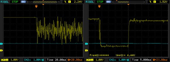
Many of us automatically go to a microcontroller when we run into a problem with a sensor, but often a simple analog filter will do the trick. The endstop in [Reinis’s] RepRap style 3D printer was giving off an unusual amount of noise when closed. When he hooked the endstop up to his oscilloscope, he was shocked to see how much noise there really was. In comes the low-pass filter. Unhappy with the response time of his low-pass filter, [Reinis] solved the problem using a pullup resistor. Two resistors and a capacitor was all that he needed to fix the problem. A great solution!
How have you used analog filters in your projects? Send us a tip and let us know!


Hi,
another possibility is to do this “debouncing” is to use a flip flop, I think there are hundreds of schematics out there how to do that.
It’s a bit better because it’s output signal has very hard and slopes.
…that, or use a schmitt trigger (arguably just as good, and simpler to implement).
A flipflop is a great solution, if you have a changeover switch; one contact sets the flipflop,and the other resets it. You get razor sharp edges, but the repeatability of the edges depends on the repeatability of the hysteresis in the switch, which can be a problem with cheap switches, if you’re using the switch for homing the axis.
If you don’t have changeover contacts, a Schmitt trigger would certainly be the next best solution, but it wouldn’t work if you feed it the signal in the first scope capture; the noise is far greater than the hysteresis could reasonable be. The most obvious solution to that would be to load the line with a fairly low resistance pull-up or pull-down resistor, like about 1k or so. The switch can easily provide 5mA through that resistor, and any capacitively of inductively coupled noise would be strongly reduced. With a Schmitt trigger (discrete device or comparator configured as a Schmitt trigger), the problem would also have been solved.
In this particular case, just a low resistance pull-up or pull-down resistor might also have solved the problem, and/or a small capacitor (a few nF, not 0.1uF) to ground would probably have reduced the noise sufficiently. This capacitor would form a capacitive voltage divider with the parasitic capacitance of the cables, which would probably only be a fraction of a nanofarad.
The problem is the high amount of noise on the wires. The best solution is to combat this at the source. For instance, make sure that the switch has its own ground wire (not shared with the motor driver). The signal/ground wires of the switch need to be twisted, and the same applies to signal/ground of the motor circuit. Try to avoid the wires being parallel and close together. Also, make sure the motor driver isn’t too noisy. Avoid razor sharp edges, and add snubbers to stop ringing. Check power supply noise. Add some extra capacitors near the motor driver if necessary.
After doing as much as possible at the source, check the noise, and if it’s still too high, add the RC filter.
Any contact bounce at the switch can be handled in software instead of adding extra hardware.
Rerouting wires and switching to shielded or twisted pairs, etc. is all well and good, but at the end of the day we’re just checking to see whether a switch is on or off, not trying to squeeze the last few Hz of RF bandwidth out of it.
Pragmatically, a little signal conditioning goes a long way here. I think the biggest issue is the internal pull-up on the control board. They’re usually pretty weak, which leaves the I/O pin effectively floating.
I accidentally reported your comment when looking for the edit button. If the mods are reading, sorry for the false alarm.
I think I came across as overly critical of solving this issue at its source. It’s a very good idea, and I agree that mixing your signal and power lines in this way is probably bad, even for something as simple as a switch. There are probably situations where you could run into real trouble by being sloppy with your wiring. I’m not sure if a printer endstop is one of them (I guess it depends on how large/powerful the printer is), but there are situations where you cannot be too careful.
Of course, if you already have a working design, adding a small capacitor to fix a problem can be acceptable. However, solving the problem properly has advantages: you learn something, and then you can do the next project correctly from the start, and also the disturbance from the motor driver may hurt the circuit in another ways that won’t show up until later. As long as it’s a hobby project, time is free, and extra experience is valuable.
Agree about the pull up/down resistor. Looking at his original circuit, there’s nothing like this, and it’s presumably relying on the weak pull up/down inside the microcontroller. With the switch open, you have a floating pin, which is a recipe for disaster.
I had always underestimated the amount of noise which can be generated by stepper motor cabling (and also spindle wiring, if you happen to have one of those high-speed VFD spindles). I was once working on some analog electronics on my bench which is at the other side of the garage from my CNC router, and I could clearly see noise pickup when the motors were running. In fact, sometimes, the noise from the VFD cabling is enough to cause the computer’s mouse to pass out ;-)
Shielded cable is the answer!
You would want to have a small SMT capacitor (say 1nF) with shortest connection to ground plane and clamping diodes right at the input entry point to handle nasty stuff like ESD or EMC anyways.
EMC can be wither from day to day stuff like a cellphone near the wire or noise from your PCB side going out to the wire.
a flipflop wouldn’t do anything to remove the noise, the only thing that helps is lower impedance, the pull-up resistor instead of the wimpy internal pull-up and the cap to low pass filter the signal
“Many of us automatically go to a microcontroller when we run into a problem with a sensor, but often a simple analog filter will do the trick.”
Actually, my first inclination would be to look at how the sensor was connected (I wish I could see his -original- schematic for the sensor); the fact that he was running the line right next to and unshielded from a power line (the stepper) – in and of itself is a big design flaw; one that should have never been done from the beginning.
After that step, then I would have dropped my o-scope on it to see what the signal looked like, and would have likely implemented something similar to the resulting circuit if needed.
I’m also not absolutely certain that he really needed to go to the trouble of making the sharper rise time, either; his first fix seems to have a more than suitable rise time; it was at 3+ volts in the first 2-3 ms, well above the needed level for a TTL HIGH signal. The mechanical “slop” in the mechanism would be slower than that, likely. But to each their own, I guess.
This is a far too common problem nowadays – fixing the symptoms rather than the cause.
No, I haven’t, because analog circuits are witchcraft or possibly black magic. Either way, my brain is way too digital to make any damn sense of it.
It looks like the controller is depending on a weak pull-up on this input pin.
Typically, pull-ups provide about 100uA to pull an input pin high to detect when the pin is grounded. If Vdd=5V, this makes the pull-up similar to a 50k Ohm resistor to Vdd. You would be able to confirm that by measuring the current that flows from the input circuit to ground when the switch is closed.
Adding the 3.3k Ohm pull-up to the input is the correct solution. The capacitor might not be required, but doesn’t hurt. It’s also extremely simple.
This also suggests a design weakness in the RepRap – a weak pull-up, and probably too much dependance on firmware to address hardware issues.
(How many programmers does it take to fix a burned out light? It can’t be done – its a hardware problem.)
Looking at the scope screenshot, it looks like there’s no problem with the pull-up, as the ‘1’ state has very little noise. The noise appears when the switch is closed. I would guess this is caused by a (thin) ground return wire that’s shared by switch and motor. Just having a separate clean ground wire for the switch would probably help a lot.
If what the other comments say is true, he should really look at fixing his wire routing. Running unshielded data lines by steppers is always bad news, and possibly damaging to boot.
Sorry, all I see from his schematics was originally grounded via a resistor or left floating, so when grounded it was not a differential between the cap + and a resistor to ground, so, in short what I see is it was done from the beginning! and the hack! was to just to it right by pulling the line high via a resistor, and ground when closed. Uhm, standard. Ditch the cap and second resistor .
this is electronics of dummies page 3!
for end stops, only buy the best switches money can buy and then debounce it with a RC low pass filter – thats it
Unfortunately, it seems the hack is leading to incorrect assumptions.
The smoothieware instructions for 3D printing concluded that you want to have the switch wired normally open. You don’t want to do that with limit switches (“end stops”) because if the switch goes bad, it most commonly stops contacting. So you want a closed circuit, then break the circuit if you hit the limit. If it’s wired normally open and the switch doesn’t close, the machine crashes the end of the travel. If it’s wired normally closed and the switch is broken so that the loop is disconnected, the machine just doesn’t move.
Thankfully, most 3D printers won’t damage themselves or people on a crash, but we continually see people trying to build larger machines, and a bigger, heavier machine can get more risky without this kind of good practice.