How any string instrument sounds depends on hundreds of factors; even the tiniest details matter. Seemingly inconsequential things like whether the tree that the wood came from grew on the north slope or south slope of a particular valley make a difference, at least to the trained ear. Add electronics into the mix, as with electric guitars, and that’s a whole other level of choices that directly influence the sound.
To experiment with that, [Mark Gutierrez] tried rolling some home-brew capacitors for his electric guitar. The cap in question is part of the guitar’s tone circuit, which along with a potentiometer forms a variable low-pass filter. A rich folklore has developed over the years around these circuits and the best way to implement them, and there are any number of commercially available capacitors with the appropriate mojo you can use, for a price.
[Mark]’s take on the tone cap is made with two narrow strips of regular aluminum foil separated by two wider strips of tissue paper, the kind that finds its way into shirt boxes at Christmas. Each of the foil strips gets wrapped around and crimped to a wire lead before the paper is sandwiched between. The whole thing is rolled up into a loose cylinder and soaked in mineral oil, which serves as a dielectric.
To hold the oily jelly roll together, [Mark] tried both and outer skin of heat-shrink tubing with the ends sealed by hot glue, and a 3D printed cylinder. He also experimented with a wax coating to keep the oily bits contained. The video below shows the build process as well as tests of the homebrew cap against a $28 commercial equivalent. There’s a clear difference in tone compared to switching the cap out of the circuit, as well as an audible difference in tone between the two caps. We’ll leave the discussion of which sounds better to those with more qualified ears; fools rush in, after all.
Whatever you think of the sound, it’s pretty cool that you can make working capacitors so easily. Just remember to mark the outer foil lead, lest you spoil everything.
[Dale Cook] has cats, and as he readily admits, cats are jerks. We’d use stronger language than that, but either way it became a significant impediment to making progress with an RFID-based sensor to allow his cats access to their litterbox. Luckily, though, he was able to salvage the project enough to give a great talk on RFID from first principles and learn about a potentially tragic mistake.
If you don’t have 20 minutes to spare for the video below, the quick summary is that [Dale]’s cats are each chipped with an RFID tag using the FDX-B protocol. He figured he’d be able to build a scanner to open the door to their playpen litterbox, but alas, the read range on the chip and the aforementioned attitude problems foiled that plan. He kept plugging away, though, to better understand RFID and the electronics that make it work.
To that end, [Dale] rolled his own RFID reader pretty much from scratch. He used an Arduino to generate the 134.2-kHz clock signal for the FDX-B chips and to parse the returned data. In between, he built a push-pull driver for the antenna coil and an envelope detector to pull the modulated data off the carrier. He also added a low-pass filter and a comparator to clean up the signal into a nice square wave, which was fed into the Arduino to parse the Differential Manchester-encoded data.
Although he was able to read his cats’ chips with this setup, [Dale] admits it was a long road compared to just buying a Flipper Zero or visiting the vet. But it provided him a look under the covers of RFID, which is worth a lot all by itself. But more importantly, he also discovered that one cat had a chip that returned a code different than what was recorded in the national database. That could have resulted in heartache, and avoiding that is certainly worth the effort too.
The BBC Micro:bit, while not quite as popular in our community as other microcontroller development boards, has a few quirks that can make it a much more interesting piece of hardware to build a project around than an Arduino. [Turi] took note of these unique features and decided that it was the perfect platform to build a synthesizer on.
The Micro:bit includes two important elements that make this project work: the LED matrix and a gyro sensor. [Turi] built a 5×5 button matrix for inputs and paired each to one of the diodes, which eliminates the problem of false inputs. The gyro sensor is used for detuning, which varies the pitch of any generated sound by a set amount according to the orientation of the device. It also includes a passive low-pass filter to make the sound more pleasant to the ear, especially for younger players of the machine. He’s released the source code on his GitHub page for anyone interested in recreating it.
While this was a one-off project for [Turi], he notes that using MicroPython to program it instead of C led to a lot of unnecessary complications, and the greater control allowed by C would enable some extra features with less hassle. Still, it’s a fun project that really showcases the unique features of this board, much like this tiny Sumo robot we covered over the summer.
Audio synthesizers can range from vast racks of equipment with modules stitched together by a web of patch cords to a couple of 555s wired together in an Atari punk arrangement. This light-controlled synth comes in closer to the lower extreme of that range, but packs a sonic punch that belies its simplicity.
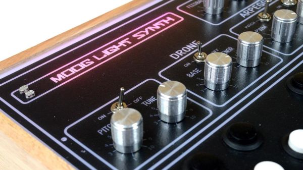
The project is the latest version of [lonesoulsurfer]’s “Moog Light Synthesizer,” which shares a lot of the circuitry found in his first version a couple of years ago. This one has a lot of bells and whistles, but it all starts with a PWM oscillator that contributes to the mean, growling quality of its sound. There’s also a low-pass filter that’s controlled by a couple of light-dependent resistors, which can be played by blocking them off with a fingertip. A couple of inverters form a drone oscillator that can be switched into the circuit, as well as a 555-based arpeggiator to chop things up a bit.
All those circuits, as well as support for a thirteen-key keyboard, live on one custom PCB. There’s also an off-the-shelf echo/reverb module that’s been significantly hacked to add to the richness of the sound. The custom wood and acrylic case make the whole thing look as good as it sounds.
We noted that [lonesoulsurfer]’s previous “Box of Beezz” drone synth seemed to evoke parts of the “THX Deep Note” at times; similarly, some of the sounds of this synth sound like they’d come from the soundtrack of a [Christopher Nolan] film — check it out in the video below.
Frequenters of arcades back in the golden age of video games will likely recall the mix of sounds coming from a properly full arcade, the kind where you stacked your quarters on a machine to stake your claim on being next in line to play. They were raucous places, filled with the simple but compelling sounds that accompanied the phosphor and silicon magic unfolding all around.
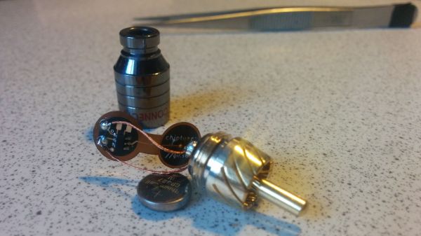
The days of such simple soundtracks may be gone, but they’re certainly not forgotten, with this chiptunes generator built into an RCA plug being both an homage to the genre and a wonderful example of optimization and miniaturization. It’s the work of [girst] and it came to life as an attempt to implement [Rob Miles]’ Bitshift Variations in C Minor algorithmically generated chiptunes composition in hardware. For the first attempt, [girst] chose an ATtiny4 as the microcontroller, put it and the SMD components needed for a low-pass filter on a flex PCB, and wrapped the whole thing around a button cell battery. Stuffed into the shell of an RCA plug, the generator detects when it has been inserted into an audio input jack and starts the 16-minute piece. [girst] built a second version, too, using the Padauk PSM150c “Three-Cent Microcontroller” chip.
Mind you, [Franco Molina]’s “DrumCube” doesn’t quite have the flash of a human drummer, but it does keep a steady beat and has a charm of its own. The drum machine is mostly mechanical, reminding us somewhat of the Wintergatan Marble Machine which is as captivating to watch as it is to hear. The DrumCube has a snare drum played by two servo-controlled sticks, a kick drum using foam waggled back and forth between two piezo transducers hooked to a low-pass filter, and a reverse-biased transistor white noise generator used for the hi-hat. Sadly, the large gear appears to be just for show. An Arduino runs everything and makes sure the mechanical drum hits are synced to the electronic cymbals, which was no mean feat.
The video below shows it in action accompanying [Franco] on his guitar, and it looks as good as it sounds. Prefer a more compact, all-electronic drum kit? Here’s one that fits in your pocket.
If you are in any way connected with radio, you will have encountered the low pass filter as a means to remove unwanted harmonics from the output of your transmitters. It’s a network of capacitors and inductors usually referred to as a pi-network after the rough resemblance of the schematic to a capital Greek letter Pi, and getting them right has traditionally been something of a Black Art. There are tables and formulae, but even after impressive feats of calculation the result can often not match the expectation.
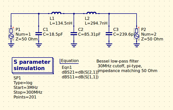
The 30MHz low-pass filter, as QUCS delivered it.
Happily as with so many other fields, in recent decades the advent of affordable high-power computing has brought with it the ability to take the hard work out of filter design, Simply tell some software what the characteristics of your desired filter are, and it will do the rest. The results are good, and anyone can become a filter designer, but as is so often the case there remains a snag. The software calculates ideal inductances and capacitances for the desired cut-off and impedance, and in selecting the closest preferred values we modify the characteristics of the result and possibly even ruin our final filter. So it’s worth taking a look at the process here, and examining the effect of tweaking component values in this way.
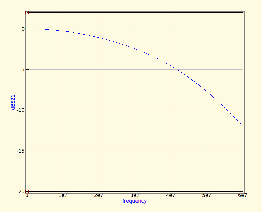
The idealised graph produced by QUCS for our filter.
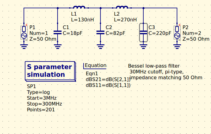
The filter we’re designing is simple enough, a 5th-order Bessel filter, and the software is the easy-to-use QUCS package on an Ubuntu Linux machine. Plug in the required figures and it spits out a circuit diagram, which we can then simulate to show a nice curve with a 3dB point right on 30MHz. It’s an extremely idealised graph, and experience has taught me that real-world filters using these designs have a lower-frequency cut-off point, but for our purposes here it’s a good enough start.
As previously mentioned, the component values are not preferred ones from a commercially available series, so I can’t buy them off the shelf. I can wind my own inductors, but therein lies a whole world of pain of its own and I’d rather not go there. RS, Mouser, Digikey, Farnell et al exist to save me from such pits of electronic doom, why on earth would I do anything else but buy ready-made?
My revised filter circuit with off-the-shelf component values.
So each of the components in the above schematic needs moving up or down a little way to a preferred value. What effect will that have on the performance of my filter? Changing each value and re-running the simulation shows us the graph changing subtly each time, and it can sometimes be a challenge to adjust them without destroying the filter entirely. Particularly with the higher-order filters with more components in the network you can observe the effect of individual components on the gradient at different parts of the graph, but as a rule of thumb making values higher reduces the cut-off frequency and making them lower increases it. In my case I always pick higher values for that reason: my nearest harmonic I wish to filter is at double the frequency so I have quite some headroom to play with.
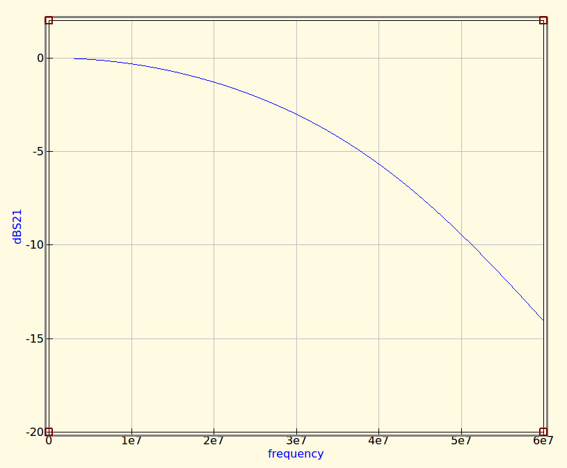
The revised curve from the filter with preferred values.
Having replaced my component values with preferred ones I can run the simulation again, and I can see from the resulting graph that I’ve been quite fortunate in not damaging its characteristics too much. As expected the cut-off frequency has shifted up a little, but the same curve shape has been preserved without any ripples appearing or it being made shallower.
If I were using this filter with a real transmitter I would ensure that I designed it with a cut-off at least a quarter higher than the transmission frequency. In practice I find the cut-off to be sharper and lower than the simulation leads one to expect, and for example, were I to use this one with a 30 MHz transmitter I’d find it attenuated the carrier by more than I’d consider acceptable. It must also be admitted that changing the component values in this way will also change the impedance of the filter from the calculated 50 ohms, however in practice this does not seem to be significant enough to cause a problem as long as the value changes are modest.
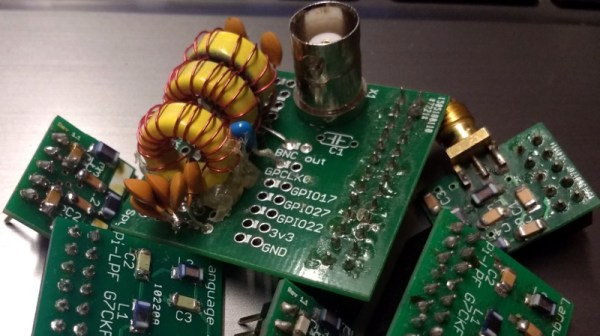
We haven’t made this filter, but in the past we’ve featured another one I did make, and by coincidence it was in the same frequency range. When I wrote a feature on automating oscilloscope readings, the example I used was the characterisation of a 7th-order 30 MHz low-pass filter. It might even be one of the ones in the header image, pulled from my random bag of filter boards for the occasion.