 Things don’t always run the way we want them to or operate at the ideal temperature out of the box. Instead of spending extra for power controls that may or may not meet your needs, wouldn’t it make more sense to dial in the ideal level from the source? That’s what [dekuNukem] had in mind when he decided to make Powerduino, an arduino-compatible programmable power strip.
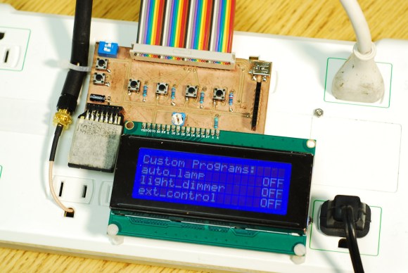
With Powerduino, [dekuNukem] can control the electrical consumption of all kinds of things without ever worrying about the irreversible deadliness of mains voltage. It actually uses a Teensy 3.1 which can be programmed with the Arduino IDE through the micro USB connector. He’s really tricked it out to the point of putting Kill A Watt meters to shame. A wi-fi module lets him control any of the outlets from anywhere, and the RTC module lets him make customized schedules for them. Powerduino has an SD card slot for logging energy consumption, and a 20 x 4 LCD screen makes it easy to directly interface with the power strip.
The Powerduino code is up on GitHub, and [dekuNukem]’s walkthrough video is after the jump.


This is exactly what I was attempting to do but with a radio controlled Arduino. Excellent execution, and it looks really good too.
This doesn’t look very safe at all.
What you’ve never seen coax coming out of a ground port before?
Low voltage control wires exiting exposed from a double insulated mains power board, no optoisolators, isn’t exactly “safe from mains voltage” …. I wouldn’t let this on my test bench let alone use it. Dangerous.
If you’ve run out of space inside the powerboard to fit everything, grab a used UPS (something like http://powerquality.eaton.com/Products-services/Backup-Power-UPS/3S.aspx?cx=22 )
keep it with no wires exiting the case, isolate any low voltage physically from high voltage with optoisolators (SSR’s often have these built in, so locate them so the high voltage side is physically isolated with no chance of shorting to the low voltage side) (if this is done sufficiently well, using the RJ11 / USB to break out arduino pins for data / programming is safe enough, but I’d probably just opt to do everything wirelessly so the UPS was stock or n/c from an external interface perspective.
If you look at the schematics, the optical isolators are indeed used on every TRAIC relay board. The low voltage circuit was separated from mains power with a transformer, and everything is grounded.
Two words: Creepage Distance.
Hooray for opto/relay. Boo for less than 1mm between neutral and the 5V line at C1 on relay_board_mech.brd.
Of course knowledge is nothing if you don’t *do* anything with it, so congrats on actually *doing* this. With a little more knowledge about mixing low voltages with mains voltages, you can make your project much safer!
You may also want to consider turning the Triac/Relay off when there’s zero *current* not *voltage*. Since you have a current sensor, that would be a fairly easy change.
For a resistive load, like a lamp, the zero current point will coincide with the zero voltage point — it acts the same. For inductive loads, there will be an offset between the two. For many inductive loads, the zero voltage crossing is the *worst* place to turn it off. That’s when the current will be at its maximum. For a relay, this means arcing across the contacts. For the Triac, this means extra heating. The size of the load will determine how many ‘hits’ the Triac or Relay can take.
You can also protect the devices against any software timing errors: add a TVS bidirectional diode across the relay contacts (it is hard to time a relay switch, after all), and add a snubber to the triac circuit.
Nice project!
Yeah.. a lot of scary happening here. It is an awesome first start. Good efforts. But some things pretty rough.
Anyway, following all the advice given should make Mk2 a pretty decent device.
That ribbon cable exiting by threading between the neutral and ground bars immediately jumped out at me though. And as others have mentioned, switch HOT.. or better, both. But just neutral is only the ‘appearance’ of being off ;)
SSRs.. optos. Move that heatsink away from the hot outlet on the lower left corner. In fact, just move that whole little board up a generous amount. It is too close to the neutral bar as well. Not critical, but you have the empty space so might as well use it for a bit more safety.
If the names in schematic are correct, the device is switching *neutral*, not line (hot). This means that when the switched load is nominally OFF the whole load is actually floating at line potential. This is unwise even on a good day. It can be positively spectacular if that load is connected to other devices (say, via USB or an audio cable).
If the load is not properly grounded by a 3-prong plug then its *enclosure* (if metal) is floating at line potential! (don’t believe that? measure it!)
Finally, if that load *is* grounded by a 3-prong then either a) its internal electronics now has line potential between its ground and the enclosure ground, or (if the internal ground is connected to chassis) b) still has line voltage energizing it. In either case, this (often) leads to undesired (sometimes fatal) behavior.
*Never* switch only the neutral line in line-powered equipment.
Looks the mistake was corrected in the actual unit. Referring to the photos, the black wire is being switched instead of the white one.
Impressive level of control and monitoring. This your MK1 version? Well, it succeeded as proof of concept. Suggest you proceed to MKII with all the AC control/sensing inside a METAL power strip with greater separation of AC and low volt ckts in two isolated compartments. Why? You’ll be living with it for 20+ yrs and Murphy’s law does rule. Did I see a ckt breaker? A puppy taught me to include a breaker in everything AC. It was sitting next to a rubber tree plant and…