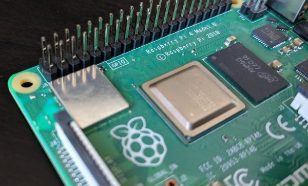
Reduce The Pi 5’s Power Consumption At A Stroke

The Raspberry Pi 5 is the new wunderkind single-board computer on the block, so new in fact that users are still finding out its quirks. One of those quirks is a surprisingly high power consumption when powered down, despite halting the SoC, it leaves the power on and consumes over a watt even in standby. [Jeff Geerling] has a solution, and it’s a simple config change.

It’s useful to know how to fix this, and we’re indebted to him for finding it, but it’s hardly the most complex of hacks. Where the interest lies is in why the board leaves the lights turned on when nobody’s at home in the first place. It seems that some HATs have an issue when the 3V3 rail shuts down, but the 5V rail doesn’t. The Raspberry Pi foundation took the most compatible route and kept the rails on all the time. Perhaps future OS releases will come up with something more elegant, but at least there *is* a fix.

If you’re new to the Pi 5, you can take a look at our review of a preview model, and see why it’s the closest yet to a usable everyday PC that they’ve produced.

RPi4: Now Overclocked, Net-Booted, And Power-Sipping

It has now been a few months since the launch of the Raspberry Pi 4, and it would only be fair to describe the launch as “rocky”. While significantly faster than the Pi 3 on paper, its propensity for overheating would end up throttling down the CPU clock even with the plethora of aftermarket heatsinks and fans. The Raspberry Pi folks have been working on solutions to these teething troubles, and they have now released a bunch of updates in the form of a new bootloader, that lets the Pi 4 live up to its promise. (UPDATE: Here’s the download page and release notes)

The real meat of the update comes in an implementation of a low power mode for the USB hub. It turns out that the main source of heat on the SoC wasn’t the CPU, but the USB. Fixing the USB power consumption means that you can run the processor cool at stock speeds, and it can even be overclocked now.

There is also a new tool for updating the Pi bootloader, rpi-eeprom, that allows automatic updates for Pi 4 owners. The big change is that booting the Pi 4 over the network or an attached USB device is now a possibility, which is a must if you’re installing the Pi permanently. There are some fixes that caused problems with certain HATs, in which the Pi 4’s 3.3 V line was cycled during a reboot.

With a device as complex as a Raspberry Pi it comes as no surprise that it might ship with a few teething troubles. We’ve already covered some surrounding the USB-C power, for example. And the overheating. Where the Pi people consistently deliver though is in terms of support, both official and from the community, and we’re very pleased to see them come through in this case too.

Watt Meter Build Walks You Through Power Measurement Basics

You almost never hear of a DC Watt Meter – one just does some mental math with Volts and Amps at the back of one’s head. An AC Watt Meter, on the other hand, can by pretty useful on any workbench. This handy DIY Digital AC Watt Meter not only has an impressive 30A current range, but is designed in a hand-held form factor, making it easy to carry around.

The design from Electro-Labs provides build instructions for the hardware, as well as the software for the PIC micro-controller at its heart. A detailed description walks you through the schematic’s various blocks, and there’s also some basics of AC power measurement thrown in for good measure. The schematic and board layout are done using SolaPCB – a Windows only free EDA tool which we haven’t heard about until now. A full BoM and the PIC code round off the build. On the hardware side, the unit uses MCP3202 12 bit ADC converters with SPI interface, making it easy to hook them up to the micro-controller. A simple resistive divider for voltage and an ACS-712  Hall Effect-Based Linear Current Sensor IC are the main sense elements. Phase calculations are done by the micro-controller. The importance of isolation is not overlooked, using opto-isolators to keep the digital section away from the analog. The board outline looks like it has been designed to fit some off-the-shelf hand-held plastic enclosure (if you can’t find one, whip one up from a 3D printer).

Although the design is for 230V~250V range, it can easily be modified for 110V use by changing a few parts. Swap the transformer, change the Resistive voltage divider values, maybe some DC level shifting, and you’re good to go. The one feature that would be a nice upgrade to this meter would be Energy measurements, besides just Power. For an inside look at how traditional energy meters work, head over to this video where [Ben Krasnow] explains KiloWatt Hour Meters


Go On A Power Trip With Powerduino

powerduino
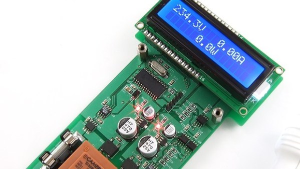
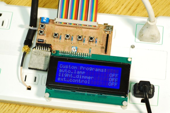
Things don’t always run the way we want them to or operate at the ideal temperature out of the box. Instead of spending extra for power controls that may or may not meet your needs, wouldn’t it make more sense to dial in the ideal level from the source? That’s what [dekuNukem] had in mind when he decided to make Powerduino, an arduino-compatible programmable power strip.

With Powerduino, [dekuNukem] can control the electrical consumption of all kinds of things without ever worrying about the irreversible deadliness of mains voltage. It actually uses a Teensy 3.1 which can be programmed with the Arduino IDE through the micro USB connector. He’s really tricked it out to the point of putting Kill A Watt meters to shame. A wi-fi module lets him control any of the outlets from anywhere, and the RTC module lets him make customized schedules for them. Powerduino has an SD card slot for logging energy consumption, and a 20 x 4 LCD screen makes it easy to directly interface with the power strip.

The Powerduino code is up on GitHub, and [dekuNukem]’s walkthrough video is after the jump.

Continue reading “Go On A Power Trip With Powerduino”

The Effect Of Code On Power Consumption

Of course putting a microcontroller into sleep mode or changing the clock rate has an effect on the power consumption of the chip, but what about different bits of code? Is multiplying two numbers more efficient than adding them, and does ORing two values consume more power than NOPping? [jcw] wanted to compare the power draw of a microcontroller running different loops, so he threw some code on a JeeNode and hooked it up to an oscilloscope.

For his test, [jcw] tested two instructions: multiply and shift left. These loops run 50,000 and 5,000 times, respectively (bit shifting is really slow on ATMegas, apparently) and looked at the oscilloscope as the JeeNode was doing its work.

Surprisingly, there is a difference in power consumption between the multiply and shift loops. The shift loop draws 8.4 mA, while the multiply loop draws 8.8 mA. Not much, but clearly visible and measurable. While you’re probably not going to optimize the power draw of a project by only using low-power instructions, it’s still very interesting to watch a microcontroller do its thing.

Open Source Wireless Mesh Networking Energy Meter

[Jay Kickliter] writes in to tell us about his open source energy/power meter. With his buddy [Frank Lynam] they designed a small device that crams into existing power boxes and uses and 8 core propeller (P8X32A) microcontroller to perform true RMS voltage and current measurements using a current transformer. [Frank] and [Jay] don’t stop there. The meter also features an xbee pro 900 MHZ to provide wireless (and even mesh networking) capabilities to the whole ordeal.

[Jay and Frank] estimate a total unit cost of around $80 (US) per prototype. With volume the price goes down by about half. With a larger number of units, and the magic of mesh networking, we could see cheaper xbee’s driving the cost down some. Check out the Google code page for details or the schematic (pdf) if you are interested.

So far the project is in the beta stages, and only features a single module sending data to a PC running an OS X Cocoa application. [Jay] is about to be otherwise occupied by the Merchant Marines and [Frank] the Navy, so they figured we could have a go at it for awhile.

We have seen other hardware used to monitor power consumption, but cramming this circuit into each power box is a neat idea.

[Frank] explains the whole project in the video after the jump.

Continue reading “Open Source Wireless Mesh Networking Energy Meter”

Clamp Sensor Power Monitoring

[Bill Porter] has joined in the pursuit of an inexpensive yet effective way to monitor his power usage. He calls his project the Not So Tiny Power Meter, and shared both his successes and follies involved in seeing it through to implementation. There are problems; sizing issues with enclosures and his PCB, issues with noise when measuring low-current signals with the clamps, and even some wireless communications issues. But it looks like he’s got the system running despite these hurdles. Right now it streams data wirelessly so that he can display the current energy consumption, but he plans to add Google Power Meter functionality next.

We’ve seen commercial units using the same sensing principles that have been hacked to show data online.