 [Texane] had been thinking about how to monitor the state of his garage door from a remote place. The door itself isn’t around any power outlets, and is a few floors away from where his server would be located in his apartment. This presented a few design challenges – namely, the sensor itself should have a wireless connection to the server, and being low power would be a great idea. This led to the development of a minimalist framework for wireless communication that allows a sensor to run for weeks without a battery swap.
The wireless protocol itself is based on a simple key value pair; each individual sensor, coupled with a NRF905 radio, has passes an address, a key, and a value. There are allowances for checksums and acknowledgement, but as the PDF says, this is a very minimal protocol.
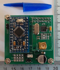
With the software out of the way, [Texane] turned to the hardware. The microcontroller is a simple Arduino clone, paired with a radio and a coin cell on a small board. The micro spends most of its time in a low power state, with the sensor, in this case a reed switch, tied to an interrupt pin.
There was a problem with the power consumption of the radio, though: when the short 17-byte message was transmitting, there was a significant voltage drop. This was okay with a fully charged battery, but with a partially drained coin cell, the possibility of brownouts was high. A big cap in parallel was enough to offset this voltage drop.
It’s still a little expensive for an all-in-one home automation and monitoring system, but developing a functional wireless protocol and the hardware to go with it is no small feat. It’s actually a great piece of kit that [Texane] is sure to find a few uses for.


If the coin cell was too small, why not use alkaline AAs? That board area in the picture is screaming “4xAA cells” in a side-by-side battery holder. In the Fine Article the total area is even bigger.
He is doing something pretty bad if the idle current is 300uA. The radio should go to 2.5uA in power down and the mico is around 1u as well.
Also, if there is so much space in the box, why bother with the expensive and hard to find CR2477 coin cell? AA is much better and easier to replace and find.
Power supply design and io states likely. Getting really low quiescent out of switchers can be tricky and getting all the pins in the right state to minimize draw can be challenging as well.
Probably the LDO (sot23-5 part in picture) itself on that “arduino” can easily draw 200uA worth of “ground current” at no load on a good day.
Isn’t micro drawing around 1uA only if all its clocks are DC? I guess it has to draw at least 5-10uA for some sort of wake up timer.
Radio receiver needs 3.65 ms to come out of power down, and then there has to be a two message duration time-window to receive one good initial message, 2×135 bits / 50kbps, or 5.4ms, or approx. 9ms total.
With my arbitrary picked values of 10uA total consumption during sleep and 20mA during awake (receiving) and 9ms of awake time, to have 300uA mean current consumption, sleep time would have to be a little above 600ms, which is borderline reasonable response time. If he wanted lower power, he’d have to accept even longer response times.
As far as I can tell, the sensor isn’t receiving anything, only sending when something happens (e.g. a door is opened). So, your calculation for “response time” seems irrelevant, and the high current consumption must come from something else.
If I recall well, protocol allows base to initiate the transfer – to ping nodes and configure them over the air. Therefore, the nodes need to listen even when nothing happens on their posts.
@tekkieneet you are right, there is a LDO on the board that I missed. This could explain the current, asuming he implemented sleep mode corectly. It could also explain his reset during the radio turn ON.
@salec, atmega328 needs 0.75uA with 32khz RTC. But it should be able to wake up on pin change without needing RTC/watchdog.
I was suggesting the use of RTC/watchdog to wake the micro periodically to send an “I am here and battery is full” every now and then.
atmega328 needs 0.75uA with 32khz RTC
Wow, that’s nice :-), I like that. My data is obviously way too old (and so are my micros). I actually googled for any RTC chip power consumption data and stumbled across a site where I found the 5uA bit, reasoned that whole microcontroller got to be less frugal then simple specialized RTC, but … surprises happen.
Oh, and as I wrote that, l checked for better RTCs and found one that goes down to 0.4uA, so the reasoning (There can always be a RTC that can draw less then a MCU) is still valid, until anyone comes with an even greater saver, but the data I selected for comparison was wrong.
Nevertheless, the mean power consumption figure is dominated by power consumption during awake state of the node, so it wouldn’t change much the analysis, even if power down consumption was flat zero.
from the website: ” power was measured to be to 300 uA at approximately 3.1 V in passive mode, with wake on interrupt enabled” so it is not the average. Still, active transmitting should be <25mA, going down to 300u average would make it a <1% duty cycle which is terribly high.
To make an example, say you open/close the door 1/hour, this gives you an average curent for transmission of 5ms/3600s*25mA = 34nA. So no, the transmit current is not dominating.
Just an idea depending on how long the door takes to open and close would placing a couple of switches in the correct location allow for the arduino to be powered off when the door is open or closed. This would mean only updating the status when opening or closing the door. Would this be more efficient or dose powering up take more power than low power mode?
Why sleeping ? you can simply connect reed switch to a latch circuit and then shutdown the whole circuit completely
If you do that you would have to initialize the micro+radio every time the switch toggles which will increase your power consumption. The sleep of the micro allows for a timer to run as well, which you could use to broadcast periodically the state of the circuit, just to make sure that it is working.
I glad to see someone using the sub 1Ghz parts for stuff like this. The longer range seems ideal for a lot of simple sensing applications. Kind of supprised that he did not go with the RF9E5 SOC for this.
I guess the arduino/atmel chip is more attractive than the 8051 in the SOC?
You can program the 8051 in c and it has a good amount of flash. The message size is 17 bytes and all the node does is report the battery level and a single switch. It should have been well within the ability of the RF9E5. Now the NRF905 might have been available on a breakout board so it would be a lot simpler to just put a prototype together with the Arduino. Heck we use arduinos at my office for testing prototype ASICs because they are cheap and easy.
True, but there are many other things to consider, for example the fact that the 8051 doesn’t have a large user base to get support from. Then tools and other….
I was checking some SOCs like this a while ago, but then I realized that for hobby it was best to stick to something I was familiar with, in my case it was atmega X and rfm12 at that moment.
This is pretty laughable. The 8051 (and variants – like the AVR aka arduino aka 40 or 50% of the consumer hacker world) are amazingly popular and years of source code, projects, examples and libraries exist. In other words, the 8051 is the jurassic era shark of all these systems – and I assure you, it’s very well supported.
The real flaw here is that the power for the unit should have been triggered by the door changing state and then shut itself back off in 3-5 seconds. You can do great things with surplus roller switches or magnetic proxy switches – just use more magnets so you get 3 or 4 pulses. Use the power to charge a cap, use the cap to power the micro.
I saw a unique version of this once, someone had stuck a pulley on a big stepper motor and run a line around the pulley from the barn door to a counter weight. They make great generators – It was connected via a really really long bit of phone cable attached to a piezo buzzer, and it would make a high pitched warbling squeak very clearly when the door was opened or shut.
I’m curious about this SOC you speak of. I have been looking for a SOC to help reduce the size of a simple transmitter. But the reference PDF Nordic supplies shows the dimensions for a PCB with this chip and it’s very big for some reason. I can’t find any examples of this chip on a pcb smaller than 3×3 cm.
The chip is only 5x5mm though so it would be very cool to see a pcb no bigger than a watch battery…
The 8051 has been around for a long time and has a huge amount of support. The real issue are you would have to make your own board and use a jtag programmer for it vs just using a USB or serial port like an ino variant.
@NoJustNo I was looking at SOCs in the 2.4GGHz band, you can find boards for nRF51822 under 2x3cm. Search for nRF51822 Beacon. Also check CC111x from TI.
@zingzing My impression is that 8051 has a legacy for being popular in products, most things developed are around expensive compilers. There is little community dealing with free 8051 tools.
This project is very easy to achieve low power. Most micro-controllers can go to extremely low power state if you wake them only by pin change(in this case the reed switch). As already pointed, the regulator is probably the one burning the power.
@Bogdan: Thanks for the information. That is extremely cool. For $30 i will have to look into it. Do you know of a transmitter with less features and a smaller size?
I won’t bother telling you to google free “open source 8051” to behold 90 zillion entries.
Since all the platforms you are using are in fact 8051 based anyway, I’m guessing some of us (myself included) interpreted your comment from the wrong side of the learning curve.
Chalk it up to the “no true scotsman” experience that provides 80% of the comments here.
Low Power analog electronics (power supplies, sensors, etc.) are a wonderful rabbit hole to go down. Enjoy!
I get 400.000 results based on your search. Replace 8051 with avr and you get in the many millions. Or with pic, or stm32 or arduino. It is not that there are no things out there, just that they are small compared to the rest of the others. The fact that other cores are derived from 8051 does not make the compiler compatible.
So you have your answer why a hobby project would be better suited with the favorite micro of your choice + some radio instead of a 8051 SoC.
@Bogdan for a prototype or a hobby device yes then you are correct. I was opening up the possibility of using the nRF9E5 SOC. The development tools actually look pretty good for it and seem like an ideal platform for little sensor nodes. It has a UART, ADCs, and SPI so it could make an interesting little sensor platform for all sorts of projects.
Why use batteries at all? We have energy harvesting sensors too. For this application I would use EnOcean contact sensor and Openremote controller.
I was blown away when I heard that the electric imp can log data every min, upload it every 15 mins and last for 1.5 years on two At batteries! Pretty insane for a WiFi device… This is cool too though :)
Are you a paid shill, or do things like this really surprise you? And what is an At battery anyway?
pardon the childish font http://www.mysensors.org/build/
What about solar, like on calculators, I was hoping our smart phones would be using solar by now?