It seems like the widespread use of delivery drones by companies like Amazon and Wal-Mart has been perpetually just out of reach. Of course robotics is a tricky field, and producing a fleet of these machines reliable enough to be cost effective has proven to be quite a challenge. But on an individual level, turning any drone into one that can deliver a package is not only doable but is something [Iloke-Alusala] demonstrates with their latest project.
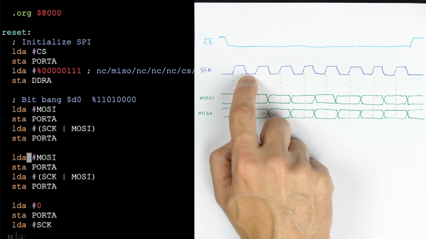
The project aims to be able to turn any drone into a delivery drone, in this case using a FPV drone as the platform. Two hitch-like parts are 3D printed, one which adds an attachment point to the drone and another which attaches to the package, allowing the drone to easily pick up the package and then drop it off quickly. The real key to this build is the control mechanism. [Iloke-Alusala] used an ESP32 to tap into the communications between the receiver and the flight controller. When the ESP32 detects a specific signal has been sent to the flight controller, it can activate the mechanism on the 3D printed hitch to either grab on to a package or release it at a certain point.
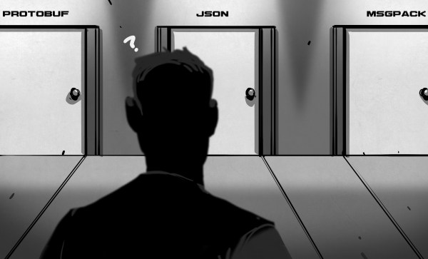
While this is a long way from a fully autonomous fleet of delivery drones, it goes a long way into showing that individuals can use existing drones to transport useful amounts of material and also sets up a way for an ESP32 to decode and use a common protocol used in drones, making it easy to expand their capabilities in other ways as well. After all, if we have search and rescue drones we could also have drones that deliver help to those stranded.
Continue reading “DIY Drones Deliver The Goods With Printed Release”