BPSK31 is an extremely popular mode for amateur radio operators; it’s efficient and has a narrow bandwidth and can be implemented with a computer sound card or an Arduino. Just like it says on the tin, it’s phase shift keying, and a proper implementation uses a phase detection circuit or something similar. [Craig] thought it would be fun to build an analog BPSK31 demodulator and hit upon the idea of doing this with amplitude demodulation. No, this isn’t the way you’re supposed to do it, but it works.
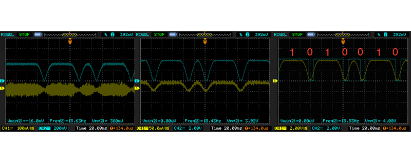
Data is transmitted via BPSK31 with a phase shift of 180 degrees being a binary 0, and no phase shift being a binary 1. [Craig]’s circuit uses an op-amp and a pair of diodes to do a full wave rectification of the signal, which basically makes a binary 1 logic high, and binary 0 logic low.
This rectified signal is then fed into a comparator, making the output go high when the signal is above 2V, and low when the signal is below 1V. That’s all you need to do to get bits out of the signal, all [Craig] had to do after that was figure out a way to sample it.
A 555 set up in astable mode running at 31.25 Hz provides the clock, synchronized with the signal by connecting the comparator’s output to the 555 trigger input. The timer clock ends up being slightly slower, but thanks to the varicode character set, the maximum number of binary ones the circuit will see is nine; every time the trigger sees a zero, the timer’s trigger is reset, re-synchronizing the receiver’s clock.
Yes, it’s a hack, and no, this isn’t how you’re supposed to receive PSK. It does, however, work, and you can thank [Craig] for that.
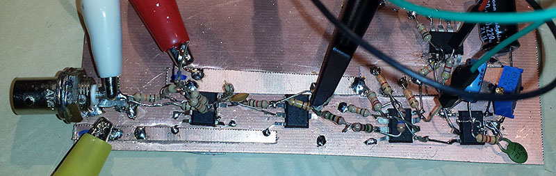


What a lovely, “messy” looking circuit. That’s how we used to prototype “back in the good old days”, before we had breadboards. Solder everything together from your hand drawn schematic, power it on and see if it works. Great job [Craig] for figuring out how to make it work the “way it’s not supposed to”.
That’s not a throwback to somebody’s “good old days”. Breadboards don’t work very well for RF projects. All those strips inside end up being capacitors. Dead bug, ugly and manhattan construction are the norm for RF projects.
Also take note that this is not an “RF” project. just built by someone who is dealing with “RF” the schematic clearly says Audio in.
Yup, no RF here, just audio baseband. Note the use of comparators though, which have relatively fast rise/fall times, i.e., their transitions have higher frequency content. A few stray pF from a solderless breadboard can cause unwanted feedback resulting in oscillations during the comparator’s transition states.
So even though the input signal is relatively low frequency, building it on a solderless breadboard is not recommended.
It’s still a good way to build if RF is involved. The stray capacitance of solderless breadboards is a nightmare at RF.
Very interesting. I wonder whether the same approach would work for AIS i.e. GMSK (Gaussian minimum shift keying)
at 9.6 kbit/s? If it did then one could build a useful and very cheap receiver for marine AIS transmissions.
I think GMSK is supposed to have a fairly constant amplitude.
Probably not. The amplitude modulation in PSK31 is used because the phase transition looks like a key-down/key-up which causes nasty harmonics. GMSK is continuous phase and frequency keyed so there isn’t really a reason to apply any amplitude modulation. You could probably hack it together with a few comparators running measuring the outputs of some narrow band filters centered at the keying frequencies and use the transitions for clock recovery like done here.
Wow, I would have never thought to try something like this, and I certainly lack the skills to make it work anyway. I guess I’ll stick to doing PSK31 the normal (boring) way.
Not to be a party-pooper, but just another among many factors to consider… this AM detection approach will only work on a quiet channel. PSK is normally decoded via DSP techniques, using narrow frequency bins. This allows many signals to co-exist within the audio passband (in fact, some PSK software can decode multiple signals in parallel). Since the decoder described here cannot discriminate signals based on audio frequency, any source of noise in the audio output from the radio would make it impossible to decode PSK – eg, lightning crashes, AC hum, goofballs tuning up on-frequency. To mitigate this, you could use super-narrow audio filters (for example, a 300Hz CW filter), but that would more than offset any cost savings to be gained from using such a simple circuit.
I applaud the creativity, but yeah, a microcontroller-based decoder would probably be a lot more effective.
This is not new but still a very good application of an old technique. When FM (mono) was first introduced most of the receivers where AM. Not wanting to re-invent the wheel, many designers just added a filter and used the output from that into the normal AM section. There were many FM signals on shortwave. All you had to do was off tune from the center frequency enough so that the IF stage filter would convert the FM to AM.
Here the input ‘1’ and ‘0’ are F and 2F (Frequency). Putting this through a low pass filter where the corner frequency is about 2F or a high pass filter where the corner frequency is about F will convert the BFSK to 2 amplitudes.
Another technique is to put it into an XOR gate and have the XOR output go to a CR network with the time constant between the two frequencies and then into the other XOR input. This XOR technique is only useful with a clean signal as the CR network only has a 45 degree filter slope whereas a second of third order analog only filter will be 6 or 9 dB per octave. Also using XOR you have a phase delay if you are recovering the original clock but you can just invert the recovered clock or trigger on the opposite slope.
It a pity that old analog techniques are not often used today. How cheap is a capacitor and resistor and perhaps an op-amp. I think it is because of the math and perhaps a phobia of op-amps. The math is so simple that it would fit on one A4 cheat sheet with big text and explanatory symbols / circuits / graphs. All you need to know is CR (filtering), CR (time constant), Xc (capacitive reactance), Xl (Inductive reactance), Corner frequency and perhaps Q factor. You could probably dice Xl altogether now days as op-amps allow you to substitute cheaper capacitors. Modern op-amps have such high gain that the math is dead simple leaving ‘offset voltage’ to be the only issue – but low offset op-amps – problem solved.
*** leaving ‘offset voltage’ to be the only issue – buY low offset op-amps – problem solved.
Very nice project! Of course doing it in software is much easier and cleaner.
BTW another thing that is missing is clock synchronization. You need a way to synchronize to the center of the bit, and also need to compensate the small clock differences between transmitter and receiver (they are very common in psk31).
There is an interesting property of bpsk31, the signal itself can be used to extract a clock signal and use it in a feedback loop to correct your reference clock.
In software this is done demodulating the signal in AM at a resolution that is a multiple of 31.25 Hz (let’s say 16x). You accumulate the average AM signal power into 16 buckets, and if the maximum is not in the 8th bucket (half) you increase or decrease the reference clock speed by a small fraction to adjust.
This is why a psk31 transmission always starts with a sequence of “idle” signal, to let the receiver synchronize its clock.
The 16 buckets can be also displayed in a histogram to reveal the “bit shape”–seeing if the transmitter has a clean signal or if it’s clipping it.
I think [Craig] has done exceptionally well with this. Sure uC solutions have their place but there can be advantages to an analog circuit as well.
A uC get the results of a math function correct for a short period of time at repeating intervals. To decrease the time between the correct results you need more MIPS. Often lots more and this eventually becomes impractical especially when the uC is required to do other things as well.
An analog circuit gets the results of a math function correct continuously.
As an example, a software PLL as you described needs signal history to align itself to the incoming clock. [Craig]’s circuit synchronizes at least once for every bit without a signal history. So [Craig]’s circuit is far superior at coping with poor signal quality, noise and recovery from signal dropout.
Sure you can do this with dedicated DSP but when you consider all the advantages of the analog circuit you find that you need a great deal of DSP resources to match the analog circuit in output quality. At that point it becomes obvious that an analog circuit is more practical and cheaper.
DSP or uC emulated DSP is better only when you need to change parameters as in SDR or it the sole function of circuit.
Analog circuits are far more practical for low MIPS uC’s where you have mixed function requirements.
+1 to [Craig] especially for the zero error precision rectifier at the front end of the circuit, I haven’t seen this used for quite some time – nice touch.
Its hackaday! I would rather have something that works, then looks pretty. Brian the 555 and 556 crew salute you!