Most of us see the world in a very narrow band of the EM spectrum. Sure, there are people with a genetic quirk that extends the range a bit into the UV, but it’s a ROYGBIV world for most of us. Unless, of course, you have something like this ESP32 antenna array, which gives you an augmented reality view of the WiFi world.
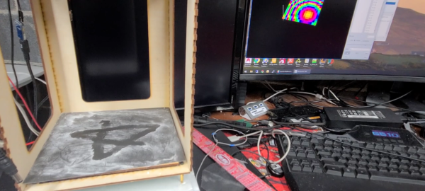
According to [Jeija], “ESPARGOS” consists of an antenna array board and a controller board. The antenna array has eight ESP32-S2FH4 microcontrollers and eight 2.4 GHz WiFi patch antennas spaced a half-wavelength apart in two dimensions. The ESP32s extract channel state information (CSI) from each packet they receive, sending it on to the controller board where another ESP32 streams them over Ethernet while providing the clock and phase reference signals needed to make the phased array work. This gives you all the information you need to calculate where a signal is coming from and how strong it is, which is used to plot a sort of heat map to overlay on a webcam image of the same scene.
The results are pretty cool. Walking through the field of view of the array, [Jeija]’s smartphone shines like a lantern, with very little perceptible lag between the WiFi and the visible light images. He’s also able to demonstrate reflection off metallic surfaces, penetration through the wall from the next room, and even outdoor scenes where the array shows how different surfaces reflect the signal. There’s also a demonstration of using multiple arrays to determine angle and time delay of arrival of a signal to precisely locate a moving WiFi source. It’s a little like a reverse LORAN system, albeit indoors and at a much shorter wavelength.
There’s a lot in this video and the accompanying documentation to unpack. We haven’t even gotten to the really cool stuff like using machine learning to see around corners by measuring reflected WiFi signals. ESPARGOS looks like it could be a really valuable tool across a lot of domains, and a heck of a lot of fun to play with too.
Continue reading “Octet Of ESP32s Lets You See WiFi Like Never Before”