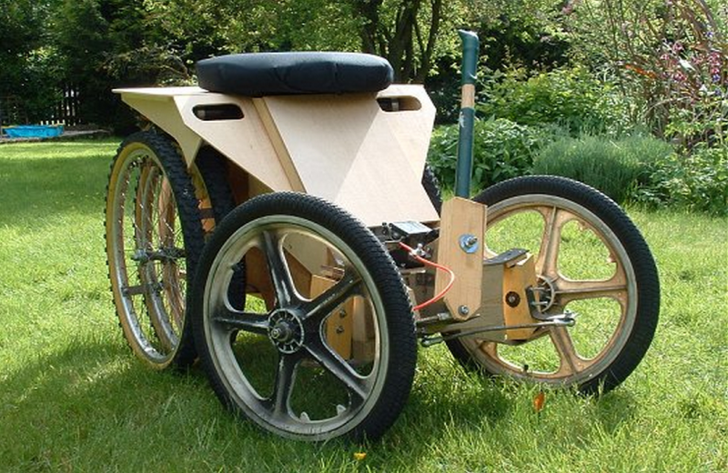
 [Ian] likes to build small Electric Vehicles and his most unique project is certainly this yard tractor. During the design phase of the project [Ian] came up with a few requirements to ensure that this vehicle would be useful around the house. First, it had to be maneuverable in tight spaces. This was accomplished by the short wheel base and small diameter front-steering wheels. Next, it had to get great traction as leaving torn-up grass around the yard was not going to cut the mustard. Four mountain bike drive wheels used in the rear double the traction while at the same time distributing the friction over twice the surface area of the grass. To increase the traction even more, the rider’s seating position was intentionally put directly over the rear wheels.
The frame was kept simple by using plywood as structural members. Two 40Ah 12v batteries are set low between the front and rear axles and power the 4 DC drive motors. The motors are connected to the axle by means of sprockets and chains which results in a 36:1 reduction. That’s a large gear reduction and limits the tractor to a top speed of 12 km/h (7.5 mph). Bike tires front and rear were used because they are easily available and are super low-cost. And of course, a tractor wouldn’t be complete without a trailer hitch to tow around plants, rocks, wood or any other general yard debris.
[Ian] makes plans for his mini EV tractor available on his website. If your kid is envious of this electric tractor, maybe you can make him one of these…


He’s using the 4QD controller – I had a really bad experience with 4QD, their customer support is terrible and both myself and my father had controllers fail for no apparent reason which they refused to repair. In my case they tried to blame battery acid for the failure when in fact I was using gel batteries, when this was pointed out they back-tracked and came up with another excuse – anything to avoid replacement under warranty it seems. I’ll never use them again – it’s not that hard to build one’s own H controllers anyway, so I shouldn’t have been so lazy.
I’ve never used any electronics package from 4QD… But if I was making a electric tractor like this, I’d use IRLZ44N’s in it.
PDF: http://www.irf.com/product-info/datasheets/data/irlz44n.pdf
Power Mosfet. 55v@47A max power. And they’re available around $2 in single quantities. There’s a newer one IRLZ44NPBF.
My dad left me 2 tubes of them, and I use them in any motor project… Even if they’re overkill (which they most assuredly are in the projects I use them).
47A only if you have an infinite heat-sink. Check the R_DS(on), and then check the graph that shows the multiplier for junction temps higher than 25°C. Multiply that by 47A to get voltage drop (>2V), then by 47A again to get power dissipated (close to 100W). Multiply that again by Rθ_JA for the package and you get >6000°C, which is probably a bit too much! If you use the Rθ_JC figure, you’re still looking at >130°C just to get heat out of the package to the heatsink, and you’ll struggle to get a heatsink that will be on par with that Rθ_JC=1.4 figure.
That said, they’re a nice grunty looking old-school MOSFET in a very tolerant package (TO220); if you paralleled a bunch up and had a powerful gate driver to get over the rather high gate charge then you could get away with some nasty current spikes.
MOSFET data sheets are a trick to read, they seem to take joy on occasion by obscuring the details you actually want quickly. All the info is there, it just needs a few sums sometimes.
Apologies if my math was off! Feel free to correct me (don’t need to ask, this is Hackaday!).
I have been messing this some fets for motors recently. To me this fet supports 55V or 47A but the power dissipation is only 110 so it is a trade off. It can’t do 55V and 47A that would be over 2k watts.
Not correct unfortunately, although I wish it were so! The 55V parameter is of no use except as a maximum voltage you can have across the drain to source. It’s not used for any power dissipation requirements; the MOSFET is dissipating the same amount of power at 55V, 10A as it is at 5V, 10A. Of course the actual thing you’re trying to drive will be dissipating different amounts of power at 55V vs 5V (at 10A), but we’re not interested in that—we’re interested in the MOSFET’s dissipation.
The only thing that matters for continuous (static) current through the MOSFET is the R_DS(on) figure, which is the on-resistance of the switch. At 25°C this is 0.022 ohms, as long as you’re using at least a 10V gate driver. You figure out what this value will be at your maximum operating temperature (this MOSFET can still operate at up to 175°C); use Fig 4 on that datasheet for this; if you say 150°C is safe, then that’s a 2x multiplier, so our on-resistance becomes 0.044 ohms.
Now you can just treat the MOSFET as a resistor, using the same power dissipation calculations you’d normally use. That on-resistance is then multiplied by the amount of current flowing through the switch; let’s say 10A as an example, giving 0.44V voltage drop across the MOSFET. Multiply this again by 10A to give us power dissipation, and you get 4.4W.
Now you know how much power the MOSFET is dissipating, you can use this to figure out if that’s going to result in a safe amount of heat. There’s some parameteres for “Thermal Resistance”. If you have no heatsink, you use the Junction-to-ambient figure, which is 62°C per watt. Multiply that by 4.4W and you get 272.8°C! Uhoh. OK, so we need a heatsink. There’s another figure, Junction-to-case, 1.4°C. This is basically how fast the MOSFET can actually get the heat out to the surface of the MOSFET for heatsinking. If we grab this heatsink: http://nz.rs-online.com/web/p/heatsinks/1898094/ then it has a thermal resistance of 14W. (1.4 + 14) * 4.4W = 68°C temperature rise. If our max ambient temp is 40°C then 40 + 68 = 108°C, well below the max junction temp of 175°C.
Repeat all those calcs for 47A and you’ll see (as in my post above) that you get some very scary numbers. Those figures MOSFET manufacturers publish are always based on the junction temp staying at 25°C—which basically means an infinite heatsink, which are pretty hard to come by (they do their testing with peltier pads and water cooling and all sorts; for us, it’s way cheaper to parallel a bunch of MOSFETs together to share the power dissipation rather than fork out megabucks for super-fancy heatsinks :). MOSFETs parallel together very well.).
Build a mower deck and That thing would be uber awesome.
It needs cat-like AI and a chainsaw attachment to reach it’s full potential.
Maybe he could add the worm neural network to it!.
http://hackaday.com/2014/12/15/gift-your-next-robot-with-the-brain-of-a-roundworm/
Cool build but the tires make me cringe:
Tractor design 101: You don’t efficiently distribute the load on soft ground by using more skinny tires…you’ll just have a rotating plow/trencher (see picture). Support is roughly (tire pressure)x(contact area) which is why large, low-pressure tires (big contact area, right?) are preferred in everything from farm equipment to “fat tire” bikes. In this case, fewer, fatter tires (even of much smaller diameter) would be preferable particularly since both the weight of the rider and the batteries are supported. Look at any commercial riding mower for the general idea.
http://bit.ly/1DPqkQ6
6 bicycle tires is definitely more then enough for yard work on grass… he probably saves a lot of weight too
There are many things about this build which may not be ideal, but coming up with something which fulfills the design goals in budget is the target here, not creating a product.
I like this hack.
the skinny bicycle wheels can be an advantage, with some ground clearance you can drive it into the vegetable garden and let a row of plants pass beneath it.
Oh! So it is a “row crop” lawn tractor! B^)
@Thinker Going by your name i’d guess you’re not that Hands-on kind of guy?
Thinkerer – and quite hands-on, thanks. I also live far from the usual hard-pack suburban lawn/garden soil, hence the comments.
Equipment out here will sink to the axles on thin tires (per the previous picture), so we have to add as much surface area as possible (read double-tires as below) or go to tracked drives. My guess is that you can clear early crop rows with them, but if the soil’s been tilled and is wet (soft), you may rethink your choices.
https://farm3.staticflickr.com/2910/14031022905_7f7dfb064a.jpg
Rats, you can’t edit these, can you? Okay, to be fair, it’s a great build and if it works for the guy more power to him – I was just adding my impressions (so to speak).
Awesome project :D
I wish I had been able to work a 2 stage gear reduction system into the project I am so diligently putting off. It sure beats the 4:1 that I’m hoping works out.
Very nicely done! For some reason, it reminds me of the Benz Patent-Motorwagen:
http://en.wikipedia.org/wiki/Benz_Patent-Motorwagen
Two front wheels with unorthodox steering system. Four rear wheels. Angular bodywork. Central driving position. It’s a Tumbler! ;-)
Absolutely cool project!
With fat bike tire the ev would look cooler but yeah it is not as low cost as 2 sets of wheels. I’ve been waiting for having some time to buy (or create ) a pedal go kart and convert it to hybrid EV.
Absolutely brilliant idea! I HATE using my riding mower as a tractor. So much noise!
Being lazy, I think I’ll get me one of them riding mowers with a shot engine cheap offa Craig’s List. I’ll scrap the mower deck and drive the existing 6 speed transmission with a geared down DC motor. You already got tight steering, floaty tires, and a hitch as purchased. I was donated an electric scooter with dead controller. It’s got beefy 24v motor and jackshaft reduction supplied. It also has two hefty 12V gel cells which still work and a fan cooled charger for them. If I can make the scooter’s controller live again, that would be totally sweet! I’ve been staring at it a long time, wondering if there wasn’t some neat thing to use this buncha parts for. Thanks again for your inspirational idea!
Such a cool project guys!
This is Really Cool! I really like the way this has been developed but needs to be very careful to use the wooden stuff in water i think so..