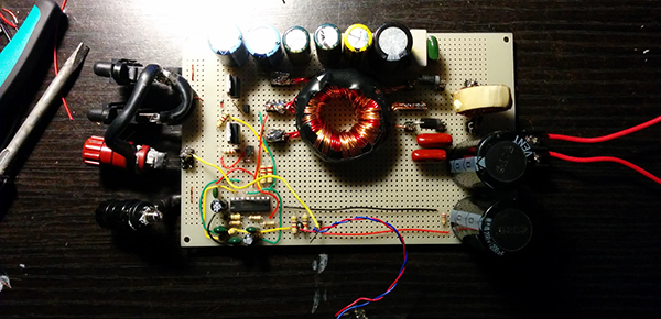
[Boolean90] needed an amplifier for a subwoofer, and had a lot of parts sitting around in a scrap bin. His project, a Class D sub amp made out of scrap, is a great example of what you can build with the right know-how and a very large pile of junk.
With digital logic and PWM chips, a Class D amp is one of the simpler ways to get a lot of amplification easily in an efficient package. It’s really not that complicated; an audio signal is turned into a PWM’d square wave, this is sent out to a Mosfet bridge, and finally out to the speaker.
Most Class D amps have a switching frequency of hundreds of kilohertz to the Megahertz range, but since this is an amplifier for a subwoofer that has a cutoff frequency of about 1kHz, the switching frequency doesn’t need to be quite as fast. [Boolean] is using a 50kHz carrier frequency; it’s more than high enough to recreate low frequencies.
With the completed project, [Boolean] has an extremely loud amplifier that has around 75-150W of output power. The subwoofer is only rated for 200W, but with the volume [Boolean] is getting, this isn’t an amp he’ll be rebuilding anytime soon.


Yep. Best way to put 20kWpk though an infrawoofer too. Sounds fine at 12kHz PWM for that though.
That’s a really cool and clean build! I wonder how long it will last in an automotive environment, though. All the vibrations and bumps from driving in addition to what the sub’s pounding out might age the perfboard and loose wires quickly. Awesome project regardless!
Add a ton of hot glue and it will last a long time. You would be surprised how much hot glue is used inside automotive electronics as a component stabilizer .
Instead of using a 25V power supply, couldn’t you use the regular 12V as supply, and then put a 1:2 transformer between the output driver and the subwoofer ?
Ah, wouldn’t work with a small transformer, because it’s not a high frequency AC signal at that point. Never mind :)
He could wire the speaker for 2 Ohms.
But the efficiency would go down considerably with resistive losses.
12V @ 2 Ohms is only 6 Amps. That’s not so bad.
Mind you, the 2 Ohms is the nominal impedance at 1000 Hz. The impedance at lower frequencies will be lower, except when nearing the reasonant frequency of the subwoofer. It’s just a standardized way to measure loudspeaker impedance and isn’t directly applicable to calculating the output power form an amp.
The AC impedance of a coil isn’t as simple as straight up Ohm’s law, because the effective Z depends on the incoming signal frequency and a host of physical factors happening with the speaker, such as the back-emf of the moving voice coil, and each frequency component in the incoming sound behaves as if there were many parallel speakers with many different impedances.
Otherwise you couldn’t possibly get 175 Watts out of a 25 Volt supply into an 8 Ohm load. A simple DC analysis would give a maximum RMS power of 78 Watts.
Thank you for your comments! Hi Dax, I do admit the upper power figure of 150W that I gave was only when I had first set the power supply’s feedback to stablize at 30-38V (38V being the maximum I was able to get from a 12v input since my transformer winding ratio was a little lacking). I then turned down the feedback potentiomenter for 25V since the primary side of the transformer ran less hot at 78W than when at power levels >100W.
Really appreciate all the feedback, thank you!
I’m having a bit of trouble figuring out what exactly the amp does with the PWM signal.
Apparently: The first stage compares the signal to a triangle ramp, which is turning the instantaneous DC value of the signal into a pulse width signal. Then it creates an anti-phase PWM signal out of that, and feeds both to a H-bridge.
But that implies, if the signal amplitude is zero, one of the PWM signals goes to zero and the anti-phase signal goes to 100%, which drives DC through the voice coil and everything goes up in smoke.
What’s going on here?
If we have a zero signal amplitude, the output of the comparator will have a constant duty cycle so the speaker would see only the 50khz carrier at that fixed duty cycle (still not good for the coil). There is an RL low pass filter in series with the speaker which will filter out anything above 1Khz so our 50Khz wave will have close to no power at the speaker ( i hear a faint “hiss” on idle but current consumption is ~70mA). The audio input will change the duty cycle of this 50Khz wave proportioanl to its amplitude. Because this audio frequency is lower than the cutoff of our RL filter, it will pass through relatively unchanged. I say relatively because as we all know, a first order low pass isn’t exactly a brick wall filter:P
Apologies, I should have made it more clear that the low pass filter is vital in the output of Class D Amplifiers to get rid of the fast carrier frequency.
On the other hand a subwoofer is a natural low pass filter, isn’t?
I wonder if those spurious high frequencies that the 1st order filter didn’t cut off make a difference.
That makes sense, If I remember correctly, the frequency response of this subwoofer was advertised to be pretty uniform for low frequencies up to 500Hz before dropping off. I could still hear higher frequencies(a little dampened) as if it were any other speaker until I used beefy 860uH inductors in series with the subwoofer and a capacitor in parallel with the subwoofer aswell. This really made a difference in only letting deeper bass hits through.
If there’s a 50/50 duty cycle PWM signal going at 50 kHz, no significant current will pass because the impedance of the voice coil at that frequency is probably kilo-ohms.
But if it’s not exactly 50/50 then there will be a DC offset to the signal, with the H-bridge switching to one polarity for slightly longer than the other and there may be significant DC current going through the speaker.
It would make sense to think that the input stage is biased around 50/50 duty cycle so that the negative half of the signal causes a DC offset to the negative and positive to the positive side, but if the biasing isn’t perfect then the amplifier will leak DC through to the sub.
Again I need to apologize for not documenting this further! On my project page, the first section about the modulator shows a picture of the circuit. The 10K potentiometer that you see in that circuit is used to apply a dc offset to the audio signal to scale it evenly over the triangle wave. If i turn this pot too far left and too far right, the subwoofer will be DC biased in either direction and I can actually physically see the voice coil push out and in as I do this (definitly dont want to do this for more than a second or two). What this means is, whenever I wire this subwoofer to a source (be it my phone audio jack or my car) I need to re-tune this potentiometer to correctly center the audio over the triangle wave. Hope that was the information you were looking for.
Why would you need to re-bias it?
The source shouldn’t affect the bias voltage in any sense, unless there’s no decoupling between the source and the input comparator.
An H bridge can pass DC through the speaker.
By shifting the audio relative to the triangle wave, you’re adding a constant offset to the duty cycle – this duty cycle bias will show itself as DC current bias from the H bridge.
The pot lets you null out the bias so that you have an average duty cycle of 50%, and a DC output of zero.
Yes, but why does the input need to be re-biased when the audio source changes?
The only reason I can think of is because the audio source is wired directly to the input of the comparator, so some of the biasing current through the pot is leaking backwards into the audio source and the bias changes every time you change the source.
Which would be bad for the audio source.
Also, if the biasing of the input stage is dependent on the audio source, wouldn’t that mean you get DC in your output if you unplug the source?
Which is also bad.
IIRC the output of the PWM signal after the mosfets would go to a low-pass filter (a coild and a capacitor); then to a coupling capacitor that would block the DC signal.
Though in some over simplified diagrams there’s no coupling capacitor.
How large of a coupling capacitor would you need to couple a 20 Hz signal at several amps?
Sounds like it would be impractical to have one in a subwoofer amp.
A better option is to drive the subwoofer straight from the low-pass filter, and use a much smaller capacitor (100uF or less) in a low-current feedback path, low-passing the output (Fc=1 to 10 Hz) to generate the DC bias currently set by the 10k pot Boolean90 mentions above.
But really, if your power supply is stable, there’s nothing wrong with manual bias control either — just put a DC voltmeter across the output and tune for zero reading.
If the input stage voltage ramp is made with a stable voltage reference, you should be able to just set and forget the bias, and the only reason you’d need to re-set is because something has gone horribly wrong.
Or if the ramp generator is unstable, you should be able to sample its signal and average it out to automatically find a 50/50 reference level.
In the TL494 datasheet:
>The oscillator charges the external timing capacitor, CT, with a constant current, the value of which is determined by the external timing resistor, RT . This produces a linear-ramp voltage waveform. When the voltage across CT reaches 3V, the oscillator circuit discharges it, and the charging cycle is reinitiated.
On these type of PWM chips, pretty much everything are referenced to the internal reference voltage. There is even a 5V reference output pin from the same source that can be used to bias the AC coupled audio signal (with the help of a pot if you like).
As [DAX] have said, it should be a set and forget design.
1. you could scrape up time to make the schematics by doing it over a weekend or maybe holiday that closes your work/school (depending if you are student).
2. if you can draw up the schematic for the power supply first that would be nice since i may be able to use the power supply in another project.
Wow… no schematics, not even a simple diagram showing by blocks what is going on. I am sorry, but most of the stuff posted on hackaday.io is extremely poor compared to other sites such as instructables.com. At instructables one typically can follow all the steps and reproduce what was done. I have *never* found so far any hackaday.io that is anywhere close to where I could build something out of the guide without having to completely re-think and re-write all the steps.