[Leo Goldstien] recently got in touch to let us know about a fascinating update he posted on the Hackaday.io page for ManiPylator — his 3D printed Six degrees of freedom, or 6DOF robotic arm.
This latest installment gives us a glimpse at what’s involved for command and control of such a device, as what goes into simulation and testing. Much of the requisite mathematics is introduced, along with a long list of links to further reading. The whole solution is based entirely on free and open source (FOSS) software, in fact a giant stack of such software including planning and simulation software on top of glue like MQTT message queues.
The practical exercise for this installment was to have the arm trace out the shape of a heart, given as a mathematical equation expressed in Python code, and it fared quite well. Measurements were taken! Science was done!
We last brought you word about this project in October of 2024. Since then, the project name has changed from “ManiPilator” to “ManiPylator”. Originally the name was a reference to the Raspberry Pi, but now the focus is on the Python programming language. But all the bot’s best friends just call him “Manny”.
If you want to get started with your own 6DOF robotic arm, [Leo] has traced out a path for you to follow. We’d love to hear about what you come up with!


…must not make fleshlight joke…
Or “goth robo GF who cooks me tendies” joke.
Nice! This is just what I’ve been looking for for a long time. Anyone can hook a few steppers to a GRBL board or maybe write a PID loop or two, but the real math where I try to remember the rest of the stuff from that one controls class I took is usually when the project goes back on the shelf.
I found this University of Queensland robotics lecture a very good refresher to all things robotics.
https://robotacademy.net.au/
Used to love doing kinematics calc exam questions with DH matrices, like 8 pages of calcs super satisfying when they fall out at the end. I wrote an RTAI kernel space driver for a PUMA560, which worked nicely but took a bit of working to nail down join acceleration limits without tripping over-torque limits or overflows punching a hole through the nearby wall.
Can this robotic arm link to a 3D print controller (Klipper)?
I guess it could? But that would come with a bunch of mechanical engineering and programming challenges… you would have 3 + 6 = 9 degrees of freedom and the weight of the robotic arm to support.
Uhm, maybe [Leo] can weigh in, but the subtitle of the post literally is “3D printed 6DOF robot arm controlled with Klipper “
It quite literally is a 3D print controller forced into the shape of a robot arm. In part 1 I cover how to adapt the klipper manual_stepper gcode command for controlling a 6dof arm.
Next step is putting the pen in the end effector. (That is not supposed to be a fleshlight joke).
I have made a CNC engraving mill and made a pen holder from an old HDD magnet, a thin piece of aluminimum angle, some wood strips and a pen all put together with hot glue. It’s quick to set up, just stick the magnet to the metal surface. The alumimimum has about 2mm of flex in Z direction so you can put a bit of pressure on the pen. And when something goes wrong, the magnet just shifts or releases, but there is no damage. Magnets don’t stick very well to plastic, but some contraption with rubber bands can also work.
I am curious to see more of this robotic arm. Usually 3D printed robot arms with plastic gears are quite wobbly and have a lot of backlash.
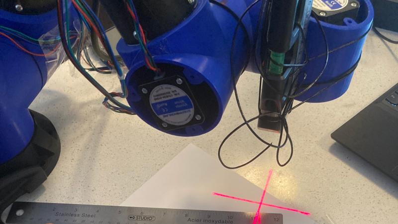
That’s a great approach. I went with a laser pointer exactly because I didn’t want to get too close to the table at this point. I’ll definitely keep this approach in mind when I’m ready for something more challenging.
As to wobbly, that was my expectation too. It’s quite surprising to me how reproducible movements can be. As a test I ran repeating movements for a dozen cycles and to the degree my camera can discern, the arm always came back to the exact same starting position.