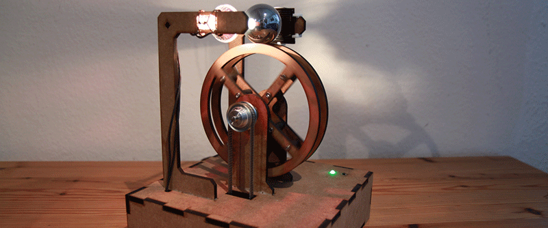
Go to any control systems class, and you’ll see a final project that demonstrates loops, integration, and everything else that can be learned in a semester or two of control theory. This project is not from one of those classes. It is, however, very cool: it balances a 40mm steel ball on the rim of a lasercut wood wheel using nothing more than a solar cell as a sensor.
[Manuel] was inspired to build this ball-balancing device after seeing a similar project at CCC about six years ago. He doesn’t remember who made it, and eschewed the PC/Matlab architecture of the original, but this build retains one interesting feature of its muse. The input to the control system is just a high intensity light bulb and a solar cell. The 40mm steel ball blocks the light reaching the solar cell most of the time. Slight variations in voltage go through the control system to keep this ball balanced on top of the wheel.
The only hardware for this build is a motor, a motor driver, and an ATMega644P. The first revision of the hardware was just a few breakout boards stuffed into a rat’s nest of wiring in the base of the build, but this has been fixed in version two with a new PCB. Video below.


That’s really beautiful. I love the giant ball bearing. A slightly smaller version would make a great desktop “toy”.
I agree altough the smaller the bearing, the harder to mantain it balanced, tough. (less mass to play with it’s inertia)
I actually started with a table tennis ball, which works really well. The relatively long spinning in one direction is a side-effect of a continous control deviation with the big ball bearing, that doesn’t happen with the table tennis ball. I have more details on this on the project page.
Love it.
These are just that kind of things that if came to crowdfunding it would attain their goals besides it’s just a “toy”.
Great looking build. This rates right up there with those magnetic levitation demonstrations.
I was wondering how it determines which direction to spin the wheel in as the main photo and [HaD] description wasn’t entirely clear.
So for those wondering, the steel ball doesn’t block the light reaching the solar cell most of the time, it aims to only block *half the light* most of the time (so if more light falls on it, the ball is rolling one way and if it blocks more then it rolls the other way – obviously the control loop will go wrong if the ball rolls too far on the dark side and it gets light again)
I was wondering how it knows which direction to go too. But.. I am thinking maybe it just assumes it needs to go the opposite of whichever way it went the previous time. Is that all it takes?
If you noticed how the shadow casted on the solar cell is covering about half on the same spot, from there you can tell which direction the ball is going: If the shadow covers more than half, the ball is going to the left. If the ball covers less than half, the ball is going to the right.
I dont think direction is controlled by the sensor system. I think it alternates direction every x seconds on it’s own in a predetermined fashion. Notice the shadow is always cast on the right side of the solar cell. When the ball moves to the left, reducing cell output voltage, it is out of balance and the wheel slows down or speeds up to compensate for ball drift. Surprised there is no Arduino or Rasberry Pi :-)
>I dont think direction is controlled by the sensor system.
It is, otherwise it wouldn’t be balancing anymore..
>Surprised there is no Arduino
“The only hardware for this build is a motor, a motor driver, and an ATMega644P”
That’s an arduino.
This was my interpretation also.
The shadow from the ball covers half of the sensor.
When you turn the device on, and the ball is in the center, the device can record the voltage on the solar cell as normal.
If the ball starts to roll to the right, less shadow falls on the solar cell, the voltage increases, the system knows to turn the wheel counterclockwise until the voltage on the solar cell is normal again.
If the ball starts to roll to the left, more shadow falls the solar cell, decreasing the voltage, indicating that a clockwise rotation is needed.
This ball has a very stable balance, it’s a very clever way to use a solar cell for position detection!
There’s no ‘OK, this is center’ step. No calibration. If the light on the cell increases, the motor will turn to pull the ball to a stationary position again.
You don’t need to know where top dead center is, because top dead center is where there is no movement.
The solar cell is a smart way to quickly and accurately determine how much of the cell is occluded by the ball. Until the sun moves and the room gets brighter, anyway.
I think there’s an automatic assumption (at least I automatically assumed it) that the light and solar cell are centered on the ball. They’re not.
The solar cell is offset so that when the ball is centered, exactly half the solar cell is covered. That way, as TacticalNinja points out, you can tell which direction the ball is going.
They way I see it, approx 2/5 of the solar panel has light all the time. Call this 2volts. So the controller will have the stepping of 2 volts. If it goes under 2v, it is one direction, if it goes over 2v it’s the other direction. It’s just an offset 0!
*setpoint not stepping. Bloody auto correct!
Why are the pictures always cut off?
What if it was pefectly PID tuned? It would move hardly at all?
Yes, that would be nice. But the motor has a gearbox, so there is back lash at direction change. So I couldn’t tune the control loop that tight, it would start to oscillate out of control very quickly. Also, looking at a stationary ball is kind of boring, I even have a function in there to nudge it back into movement, if standstill happens :)
Wow, That’s pretty cool. I’m surprised at how much the wheel had to move…I expected it to just stutter back and forth like a balancing bot.
lol… i thought it is powered by a solar cell when I read the title… Using a solar cell as a sensor definitely makes more sense….
Wow, thanks for putting my project on the blog, so that’s where all these followers come from! I was kind of expecting a message or something to let me know my project is on here (not that I’m complaining of course :)
Wow, thanks for putting my project on the blog, so thats where all the followers come from! I kind of expected a message to let me know, not that I’m complaining of course…
Seems like this could easily have been done completely analogue? IMO that would have been even cooler than using a micro controller for this.
Could….this be a hardware random number generator :D