So you just scored a vintage piece of test gear, or maybe you just bought a fancy new DMM (Hmm…We love that new multimeter smell!) But can it read voltage accurately? How can you be sure? Well, that’s why you should build yourself a voltage reference box.
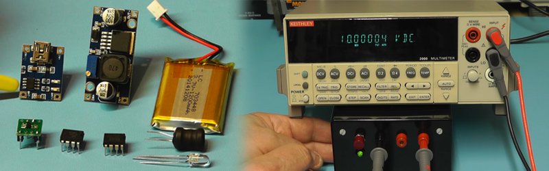
Youtuber [Scullcom’s] latest video has you covered. Wants some specs? Sure. How does a precision 10v and 5v output with only ±0.025% and an amazing 2.5ppm/°C sound? That’s very impress for something you can cobble together yourself. We find it interesting that he actually uses some ebay parts to pull off this build. The LiPo battery, USB LiPo charging circuit, and boost regulator are all sourced from ebay. Not to worry though, as these parts are only used to supply power to a 15 volt linear regulator. The real magic happens in the Texas Instruments REF102 precision voltage reference. You give it a decently clean 12-36 volts, and it will give you a 10 volt reference out. These amazing chips are able to obtain such precision in part because they are calibrated (or more specifically “laser trimmed”) from the factory. A secondary output of 5 volt is achieved by using a differential amplifier.
Warning: The video after the break is a bit on the long side(43 mins), so you might want to make some popcorn. But we find [Scullcom’s] teaching style to be lovely, and he does a wonderful job of explaining the project start to finish, soup to nuts.


The REF102 is a really nice device. But for 5V there are even more accurate references available from Intersil (the ISL21009 series). I used them in my MultiRef project (http://blog.hendriklipka.de/archives/2014/05/volt_multi_ref.html ) which gives 5 different voltages to span all DMM ranges I might encounter.
For a hobbyist its one of the best options next to buying a DMMCheck or something similar – not everybody can afford a HP / Agilent / Keysight / whatever-brand 7.5 digit bench multimeter :(
i have done this before with the LTZ1000 … waste if money (vs a 399) as proper heat isolation was not obtained XP
The ISL21009 line is not actually all that great for its cost … 5ppm 1.5% … I prefer the ti ref50xx 2.5ppm line for cheap calibrateable stable references with good initial accuracy … Cheap and great for General adc applications
Where did you get these number from? The ISL21009BFB850 is a 5V, 0.01%, 3ppm/°C reference (so it has a 0.5mV error). And its even slightly cheaper than the REF102C that [Scullcom] is using.
I’m using my reference for checking the long-term stability if my DMMs. Using a reference with 10 times the accuracy of my DMM (and a known drift) allows me to see whether they run out of spec or not.
Forgive my ignorance but what is exactly this ppm/ºC thingie?
I’m only used to ppm as parts per million for concentration ‘-‘
It’s ppm (parts per million same as percentage in a solution but in this case referring to voltage) change per *c of ic temperature change from initial calibration
I bought some Geller Labs voltage references (5 ppm) before he went out of business :-(
I *believe* schematics are still on his web site.
http://www.gellerlabs.com/SVR%20M%20assmbly.html
It’s amazing to me how today, an amateur can purchase equipment that rivals the accuracy of equipment I was using in my youth as a grad student. The atomic clock time standard available over GPS is another example.
A few of years ago I set up a laser interferometer on my kitchen table to measure the deflection of a piezoelectric transducer. It worked, and only took me a couple of hours to set up.
It’s quite easy to do really accurate measurements nowadays – I’m surprised there aren’t more amateurs doing interesting research. Lots of things in the style of “Scientific American Amateur Scientist” would make a publishable paper.
(Or maybe there are and I haven’t heard of them?)
I loved the “Amateur Scientist” articles. I have them all on CD-ROM now. It’s amazing how complex / dangerous some of the projects are- a cyclotron, lasers, a plasma MHD device, and so forth.
Other than bragging rights, why would an electronics hacker need a precision reference?
I know I could use it to calibrate my dmm, but don’t know why it really matters if my meter is off by 1%.
Precision measurements aren’t needed for electronics hacking. When you’re designing circuits, everything is only within 20% of the calculated range anyway.
You need precision measurements to do data collection.
For example, suppose you want to measure the energy output of a battery over time, compare capacitor charge/discharge rates across vendors, or local temperature as translated to voltage.
Suppose you want to recreate the Millikan Oil drop experiment, or do a similar sort of measurement.
http://en.wikipedia.org/wiki/Oil_drop_experiment
In those cases you might want something that’s more than 1% accurate, and is temperature stabilized.
When you’re designing circuits to measure things, you can spend tens of hours researching what resistors to use in a divider, and every ppm and every tenth of a percent here or there add up.
That’s still hacking, just a bit of a different breed!
I think you have to consider 1% of what? Usually it’s the range that the meter is set to. When I’m trying to measure microamps for a device that has to work for a few years on a coin cell a 1% difference in the 200uA range equates to a big difference in the lifetime of the device.
I’m not sure he’s correct there to allow the battery to be discharged below 3.7 VDC, down to 3.1VDC. Usually Lithium batteries have a useful voltage range of 3.7-4.2 VDC, and if you drop it below 3.7 VDC the battery has to be trickle charged to 3.7 VDC first before you can fully charge it again.
I’m a bit puzzled because his LiPo cell does seem to have a protection circuit, which normally guards against undervoltage conditions.
Perhaps he’s got a LiFePO4 battery, of which Wikipedia says it’s fully charged at 3.6-3.8 VDC?
A LiPo cell can be discharged safely down to about 3.0V. A typical trickle charge (for deeply discharged cells) charges up to 2.9V and there the normal charge cycle starts (look e.g. at the LTC4054 datasheet).
I don’t know where you are getting your information, but it is wrong. Most lithium ion batteries can be and are discharged far below 3.7v. Battery manufacturers typically state capacity by measuring discharge to 2.5-3v (depending on chemistry and intended use). Protection circuitry usually kicks in at a slightly higher level, and, depending on application, the device will power down at a somewhat higher level still. Cutting discharge at 3.7v would leave half or more of the capacity unused.
A precision voltage reference, that is powered by USB and a cheesy Chinese switching regulator?
Dude. Use two 9V blocks in series instead. They’ll last for years.
Very impress. Much Precise. Wow.
Reblogged this on Julio Della Flora.
Am I missing something or adding the trim pot will introduce temperature drift, not to mention drift due to the pot inherently changing value as even multi-turn pots are notorious for. If you must have the trim pot, shouldn’t it be added as the smallest resistance element in a temperature compensating resistive ladder?
If you examine the schematic of the REF102, there is an embedded op amp. The trim pot is placed so it forms a variable voltage divider in serial between the output and the inverting input, and parallel between the inverting input and ground. This is the usual way to program any op amp.
So, you’re not actually trimming the device output directly, but rather you’re trimming the op amp gain, which is less fraught with agony..
How is the INA105 offset voltage (125 uV max) handled? If not trimmed it will appear the the 5 V output.
Why to worry about details..only resistors could go up to 100ppm per degree ..soo why to worry about details…
I work in medical and similar fields, i use 2 6.5 digit meters, bought a LTZ1000ACH board aged for 5,000 hours and have several sub-standard voltage references, as well as transfer standard thermometer (+/-0.01 C from -20 to +100), resistance references 0.01% 50ohm-1Mohm, 1% 100microhms-1ohm, 0.05 ohm 1ohm-10ohm, pressure calibrators to 0.1mm water, gauge blocks 0.1mm-100mm within 0.05 micron, capacitors +/-0.5% (restricted frequency and voltage ) , masses from 10milligram to 1Kg M1 standard (about 10mg at the 1kg level from memory). like balancing batteries for artificial hearts, these are done to 0.5mV at 4200mV – so i part in 8400 or about 0.01% – looking at an 8,5 digit next financial year.