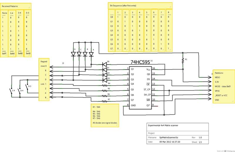
16-button keypads have a clever method of encoding their data into 8 pins. Pins are mapped to four rows and four columns on the keypad. A user reads the keypad by bringing each row up to logic: HIGH, and reading the corresponding column values, (HIGH or LOW). Keypad scanning can be farmed out to a microcontroller with a simple finite-state machine and some button debouncing techniques. [Mario], [Glen], and [Paul] on the Netduino forums took an entirely different route: they’ve designed and implemented a Keypad Scanner using any microcontrollers SPI peripheral and a 74HC595 Shift register.
The trio’s solution is an elegant adventure into circuit design. With two diodes and a voltage divider, they devise a simple circuit that pulls the SPI MISO line LOW if a button in the corresponding circuit’s row is pushed closed. Copied four-fold, this circuit joins the rows and columns of the 74HC595 to the keypad matrix. To scan across the four columns, the microcontroller performs an SPI transfer of the key value: 0x01. To decode which button is pushed, the value received back from the SPI bus encodes which button was pushed out of the 16 possible buttons. Note: some cases for ambiguity as to “which button was pressed” do exist if multiple buttons are pushed at the same time, but for the general case where we’re punching in values one-by-one, this circuit works perfectly.
The team’s hack is a clever use of existing hardware to outsource a microcontroller’s software problem to hardware while leveraging the SPI peripheral to cleverly decrypt and retrieve data back from the keypad. Kudos to the team of three over at the Netduino Forums, and we’re always thrilled to see and idea grow from one person to the next. In case you want to take a step lower and build up the keypad itself, here’s a blast from the past that does just that.


Trying hard not to rain on anybodies parade here but….
Figured this out about 15 minutes after reading the 74HC595 data sheet. I regularly use this to feed DIP switch settings back into a micro on startup and to interface countless mini keypads to a MCU. Especially if I’m using SPI for other chips already.
I’m not taking issue with the *duino guys on this but with the use of the words “clever” as if no one else has yet come up with it before.
While reading a block of DIP switches with an HC595 is pretty straightforward, reading a keypad arranged in a 4 x 4 matrix with a single HC595 is not trivial.
I am an electronics newb. Could you clarify how the DIP switches differ from keypad presses?
I assume this relates to a DIP switch simply turning one line on or off, whereas a keypress is mapping input voltage from one line to a specific but different output line. Is it the serial versus matrix nature that makes the difference?
I have a project to use the keyboard from a 1990 Toshiba laptop as a USB keyboard (it has an amazing keyfeel). Thus I am very interested. So far I’ve made a 2×3 matrix of buttons on a breadboard (with 1N1448 diodes) work with an Arduino. I am now testing a 4×5 keypad as part of a slow move toward the 8×11 matrix of the Toshiba.
Assuming enough dip switches are in use, they would be wired the same way as a keypad. The only difference I see would be the addition of switch debounce, and rescanning. (Instead of an initial scan once)
But don’t fret, Hack-a-day has been posting things that have long since been done before. The point still remains that they get visitors, and not all visitors have ‘seen’ this done before. It may be best to talk to the creator about putting his references on his project page instead of Hack-a-day for not googling around and checking time-stamps on who might have done it first.
@Mike
I know of an astronomically small number of mini keypads that are not matrix. Figuring out how to deal with a matrix of buttons really should be one of the top order things taught/learned.
@pseydtonne
Gryd3 is in the ballpark. Not much difference save for debounce code which you can use the same routine anyways to save space if you’re willing to trade off a smidge on the read speed.
I do a lot of odd bit number stuff, eg I might need only 6 bits from the *595 so I can use two towards a DIP for configuration options. Or I might have a 3×4 matrix to which I might toss a 8 bit DIP on the last row. Easier than it seems since the *595 has that squirelly bit on the wrong side.
Just don’t go crazy chaining too many together and you’ll be ok
Nothings new under the sun. If they didn’t consult you, its not in the datasheet, and its not in some standard manual they read then they came up with it, and its clever. Unique.. unprecedented.. undiscovered.. are all words a lot closer to your use.
See here to read a 3×4 matrix with just 1 ADC input, resistors and a cap. http://www.avr-asm-tutorial.net/avr_en/keypad/keyboard.html
So really need to broaden your horizon a bit. If that’s considered as “clever”, then using ADC to read the keyboard matrix would be “super genius”. I would consider the ADC one as clever.
Spoken like a true genius