Unique LED Display Inspired By Fighter Jet Dashboard

Last year, [Mangy_Dog] was asked by a few friends to consult on a project they were working on. The goal was to build an authentic replica of an F-18 cockpit, apparently for the purposes of creating a film. The project never materialized, but it did inspire him to take a hard look at the 1970s era alphanumeric displays utilized in the real aircraft. One thing lead to another, and he ended up using his own take on the idea to build his own “starburst” digit display.

As [Mangy_Dog] explains, while the faces of these original displays might have been quite small, there was a lot going on behind the scenes. Due to the technical limitations of the time, each alphanumeric character was made up of an array of incandescent light bulbs and fiber optic cables. This worked well enough, but was bulky and complex to manufacture.

Today, we can do better, even on the hobbyist level. As it turns out, 0402 LEDs are just about the right size to recreate the segments of the original starburst displays. So [Mangy_Dog] came up with a simple PCB design to not only align the LEDs properly, but drive them with a 74HC595 shift register and an array of MOSFETs. While assembly wasn’t without its challenges, he made good use of his custom built reflow oven to get all the diminutive components in place.

He went through a few different ideas for the diffuser, but eventually settled on black plastic with tiny holes drilled through courtesy of his laser cutter. Behind each set of three holes is a small pocket that got filled from both sides with transparent UV resin, which was then sanded down after curing. The end result isn’t perfect as you can still tell the center dot is brighter than its peers, but the overall effect is still very nice and definitely has a sort of faux-retro appeal.

The military naturally has access to some incredible technology, though they have a tendency to hold onto it for decades. That an individual with a meager budget and homemade tools can improve upon a piece of hardware installed in a $60+ million airplane is a testament to just how fast things are moving.

Continue reading “Unique LED Display Inspired By Fighter Jet Dashboard”

Stylish Thermometer Is DIY Hardware Perfection

Over the last few years, we’ve seen a steady improvement in the sort of custom hardware a dedicated individual can produce. With affordable desktop 3D printers and PCB fabrication services, the line between store bought and home built can get very blurry. This slick MQTT-connected thermometer created by [Martin Cerny] is a perfect example.

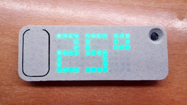
The case for the device, which [Martin] calls Temper, is printed in a stone-look PLA filament and has been carefully designed so that LEDs shining behind it illuminate perfect square “pixels” on the front. There’s a living hinge button on the left side, and on the right, an opening for the SHT30 temperature and humidity sensor. Some may say that the look of the sensor aperture could be improved with a printed grille, but there was likely a concern about reduced airflow.

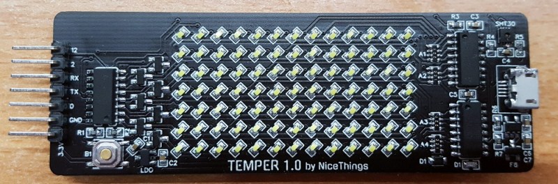
Inside the case is a 13×7 array of SMD LEDs, a few 74HC595 shift registers, a TP4054 charging chip to keep the internal 250 mAh battery topped off via USB, and some passives to round out the party. The ESP-12E module that brings it all together and the battery are on the flip side of the PCB. At a press of the button, the display fires up for 5 seconds and Temper publishes temperature, humidity and battery percentage through MQTT. If you’re looking for more granular data, it can also be configured to publish regular updates at the cost of increased energy consumption.

The physical product is gorgeous on its own, but we’re happy to report that the firmware and documentation have been handled with a similar attention to detail. The project’s GitHub repo has a Wiki to help others build and configure their very own Temper, and the device’s web configuration portal is easily just as nice as anything you’d find in a piece of modern consumer electronics (if not moreso).

We’ve seen plenty of ESP8266-based environmental monitoring devices here at Hackaday, but we think this one really pushes the state-of-the-art forward. This is a device that wouldn’t be out of place on the shelf at a Big Box electronics retailer, and while [Martin] says he has no interest in building and selling them himself, we don’t doubt that folks out there will be spinning up their own Temper clones before too long.

Chaining Together A 16×2 Bubble LED Display

We’ve recently noticed an uptick of interest in so-called “bubble displays”: vintage alphanumeric LEDs which are probably best remembered as being used in watches and calculators before the LCD took over. Today they’re available as surplus or even salvage for literally pennies, but unfortunately they only provide four or five characters to work with. Or rather they did, until [sjm4306] built a board that chains them into a 16×2 array.

For the princely sum of 71 cents each, [sjm4306] picked up ten HPDL-1414 displays, each capable of showing four characters. He then designed a PCB that would accept eight of the displays at once, and even thought ahead to use headers so they could be pulled out and swapped as needed. Of course mounting them is only half the battle, you still need to drive the things.

Each display has its own dedicated driver chip on board, but trying to address each one individually would take far too many pins. So [sjm4306] opted to use a trio of 74HC595 shift registers, allowing him to toggle the three dozen pins necessary over SPI from a microcontroller. He’s even written up a little library and some example code that you can grab on the project’s Hackaday.io page.

Unfortunately, after all his hard work, tragedy struck. As these displays were a couple decades old given their date code, [sjm4306] thought he would clean them up with a bit of alcohol before their big video debut. But whatever plastic the clear panels are made of didn’t take kindly to the IPA, and they all shattered. They still work, but it’s definitely a quirk to keep in mind if you pick up some of these vintage displays to play with yourself.

In the past we’ve seen a much smaller PCB that allowed similar displays to more easily be interfaced with modern microcontrollers; perfect if you just want to bang out a few retro LED characters with a minimum of fuss.

Continue reading “Chaining Together A 16×2 Bubble LED Display”

Lots Of Blinky! ESP32 Drives 20,000 WS2812 LEDs

20,000 LEDs sounds like an amazing amount of blink. When we start to consider the process of putting together 20,000 of anything, and then controlling them all with a small piece of electronics the size of a postage stamp, we get a little bit dizzy. Continue reading “Lots Of Blinky! ESP32 Drives 20,000 WS2812 LEDs”

Crawling A Dungeon, 64 Pixels At A Time

The trend in video games is toward not being able to differentiate them from live-action theatrical releases, and games studios are getting hard to tell from movie studios. But quality graphics don’t always translate into quality gameplay, and a lot can be accomplished with minimalist graphics. Turn the clock back a few decades and think about the quarters sucked up by classics like Pac-Man, Space Invaders, and even Pong if you have any doubts about that.

But even Pong had more than 64 pixels to work with, which is why this dungeon-crawler game on an 8×8 RGB matrix is so intriguing. You might think [Stolistic]’s game would be as simple as possible but think again. The video below shows it in action, and while new users will need a little help figuring out what the various colors mean, the game is remarkably engaging. The structure of the dungeon is random with multiple levels to unlock via the contents of power-up chests, and there are mobs to battle in a zoomed-in display. The game runs on an Arduino Uno and the matrix is driven by a bunch of 74HC595 shift registers.

It’s fun to see what can be accomplished with as little as possible. Looking for more low-res goodness? Check out this minimalist animated display, or a Geiger counter with a matrix display.

Continue reading “Crawling A Dungeon, 64 Pixels At A Time”

Simple Keypad Scanning With SPI And Some Hardware

16-button keypads have a clever method of encoding their data into 8 pins. Pins are mapped to four rows and four columns on the keypad. A user reads the keypad by bringing each row up to logic: HIGH, and reading the corresponding column values, (HIGH or LOW). Keypad scanning can be farmed out to a microcontroller with a simple finite-state machine and some button debouncing techniques. [Mario], [Glen], and [Paul] on the Netduino forums took an entirely different route: they’ve designed and implemented a Keypad Scanner using any microcontrollers SPI peripheral and a 74HC595 Shift register.

The trio’s solution is an elegant adventure into circuit design. With two diodes and a voltage divider, they devise a simple circuit that pulls the SPI MISO line LOW if a button in the corresponding circuit’s row is pushed closed. Copied four-fold, this circuit joins the rows and columns of the 74HC595 to the keypad matrix. To scan across the four columns, the microcontroller performs an SPI transfer of the key value: 0x01. To decode which button is pushed, the value received back from the SPI bus encodes which button was pushed out of the 16 possible buttons. Note: some cases for ambiguity as to “which button was pressed” do exist if multiple buttons are pushed at the same time, but for the general case where we’re punching in values one-by-one, this circuit works perfectly.

The team’s hack is a clever use of existing hardware to outsource a microcontroller’s software problem to hardware while leveraging the SPI peripheral to cleverly decrypt and retrieve data back from the keypad. Kudos to the team of three over at the Netduino Forums, and we’re always thrilled to see and idea grow from one person to the next. In case you want to take a step lower and build up the keypad itself, here’s a blast from the past that does just that.

Learn Shift Registers Without Involving A Microcontroller

This is a truly hands-on approach to learning. [Kevin Darrah] ditched the microcontroller and is using push buttons to learn about 595 shift registers. The test rig uses two of the serial-in, parallel-out chips. These are cascading which means that as data from the first chip overflows it feeds the input of the second. The parts are commonly used to drive LEDs, or reduce the number of pins needed to drive peripherals like this character LCD.

The five push-buttons give you a chance to intuitively learn how the chip logic works. The blank button is also commonly called Output Enable (OE). Driving it high shuts off the outputs of the chips but doesn’t clear the data. That task is performed by the clear button which is driven low to set all of the shift register memory to zero. The other three buttons set the logic level, shift it into the chip using the clock signal, and push the stored values to the outputs using the latch.

To get a visual approximation of what’s happening inside of these chips you should check out the shift register tutorial linked to in this post.

Continue reading “Learn Shift Registers Without Involving A Microcontroller”