While OSHPark, Seeed Studio, and DirtyPCB have taken most of the fun and urgency out of making your own circuit boards at home, there are still a few niche cases and weird people who like to go it alone. For them, [Jarzębski] has created the ultimate homebrew PCB manufacturing solution (.pl, here’s the Google translatrix).
[Jarzębski] is using UV-sensitive photomasks for his PCBs, but he’s not doing something simple like a blacklight to develop his boards. He’s using a 30 Watt UV LED for exposing his boards. This, of course, generates a lot of heat and to mitigate that he’s added a Peltier cooler, temperature sensor, and a fan to cool off this retina-burning LED. 30 Watts will get the job done, considering [Jarzębski] was using a quartet of 4.5W LEDs before this build.
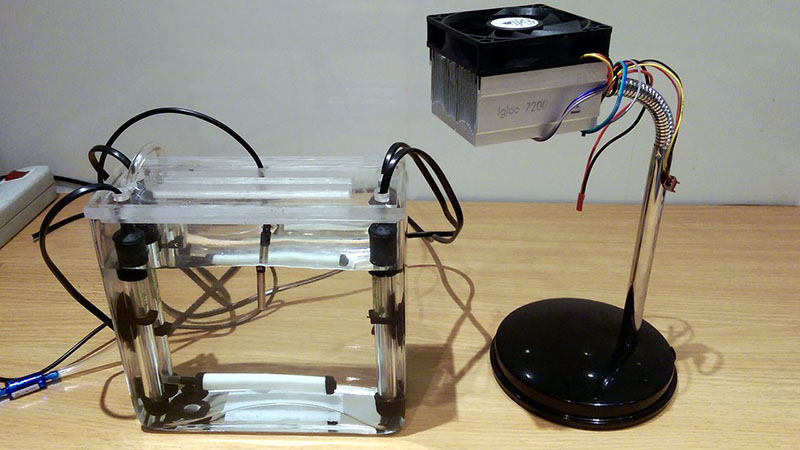
Developing a PCB is only one part of the equation; you need to etch it, too. For this, [Jarzębski] is using a small 1.6 Liter aquarium and four aquarium heaters for dunking 120mm x 120mm PCBs in the tank. There’s no mention of what chemistry [Jarzębski] is using – ferric chloride, cupric chloride, or otherwise – but the heaters and aerator should make etching go very smoothly.
There’s a video (English) going over the rest of the project below.


I am using Ammonium Per-Sulphate @ 70°C. Would the silastic in a fish tank stand up to that and would those fish tank heaters get the solution up to 70°C?
I am using Sodium persulfate (B327) for etching and UV developer (AGT-087). At the end of electroless copper tin :) I’m update post today with example photos.
Depending on model you may need to defeat the thermostat. Most fishtank heaters I’ve seen have a maximum setting somewhere in the mid 30s.
Cough cough http://youtu.be/mzmjGz0_joM?t=30s cough ahem.
Most of us will have the space for that.
Ima etchin with ma lazor! PWAAAAAAAA!
Sorry! I have to say that :p
When I first started out in electronics hobby I etched my board and found satisfaction in producing it (using poisonous chemicals that was 20years ago). Then I discovered spice program. This made me rethink my electronic hobby and tried all kind of simulations with no manual labor to build anything. I even got all the test equipment on software without buying the costly test equipments. :D
I got back to the real tangible electronic projects when the micro controllers became cheap and super tiny, you can now buy complete devices and connect them together and you got something really usable and more fancy than an electronic radio or a wireless mic.
I know we can now print PCBs like paper and use them on projects I just hope people have access to them and they are more affordable so we get another revolution in the hobby.
Why on earth do you want to use a Peltier to cool that LED? It just makes a lot of more waste heat that the heatsink will need to dissipate …
Peltier cooler for an LED? That’s pretty stupid. The LED doesn’t need to be much cooler than about 50C and the Peltier merely increases the load on the heatsink by a factor of about 5 because they’re so damn inefficient.
I built a little hack with a 30W UV LED (365nm). I use it for UV-fluorescent photography; you can see the light and some results from it here. It’s an oversized heatsink, about 0.4K/W in still air, because that’s what I had handy and I could fit the controlled-current supply on there too. All off-the-shelf bits (PSU, light switch, heat sink, COB LED); the U340 excitation filter is mounted in a 72-58mm step-down ring that’s screwed into the heatsink around the LED.
You’re absolutely right :) But during the design, I was interested in them, and I thought it would be fun to learning about their properties.
I agree with you 100%. Peltier is redundant, but when building it, I was interested in Peltier and I had great fun in discovering the properties on :) As it is, it is.
I wouldn’t call a peltier usage “pretty stupid” at all. They are inefficient, but who cares if he doesn’t care about efficiency. And he can still get colder temperatures than without one. And it doesn’t matter if he increases the load on the heatsink if the heatsink can handle it. Like he said, he was also using this as a learning experience about them. Are you always a moron and crawl out of the woodwork to insult/demean people’s work for no good reason?
A peltier is actually a pretty smart move.
The nominal output figures, efficiency, radiation power etc. for any LED are measured at a junction temperature of 25C which means it has to be de-rated for an actual use case.
The output of the LED varies with temperature, so using a peltier with a thermistor feedback will allow you to stabilize the light output and get exact timings for the exposure regardless of ambient temperature or whether the heatsink starts off warm or cold.
And if anyone is thinking about making/using one of these, make sure you have eye protection. Simple polycarbonate goggles are fine.
A 30W LED will make your eyeballs fluoresce. A few minutes of exposure will give you conjunctivitis (UV burns to the eyes) just like unprotected arc-welding.
Of course I use goggles with UV protection
Conjunctivitis is an infection or reaction to a foreign body. The condition you’re after is photokeratitis, essentiall a sunburnt conjunctiva.
Mind you the name of it doesn’t make it any less dangerous. Conjunctivitis can be a mild nuscience. Photokeratitis on the other hand is usually quite painful.
Not to diminish the good advice regarding eye protection, UVA (320-400 nm) radiation is relatively benign if you’re not stupid about it. Workplace 8-hr MPE for UVA radiation is 1 mW/cm^2, which means you will have to be staring into an unprotected 30W 365 nm LED from less than a meter away for a long time to get a dose to be worried about. The 254nm from a mercury lamp is an entirely different scale, and just a minute or two near a 18W bulb will give you sand-in-eyes grief for days (yes, this I know from personal experience, making boards this way in the ’80s).
I think the toner transfer method is superior. No special sensitised boards. No UV. Etch with hydrochloric acid and hydrogen peroxide (or what have you).
Almost. IT depends on how fine a trace your board needs to have. Photoetchant is what you can use down to nm scale objects. The smallest I need can be drawn with a sharpie, but leet haxors and talented diy folks might not find my doodles and toner transfer adequate.
Seriously? Toner transfer is a cheap kludge that’s only really suitable if you’re doing through hole Arduino shields.
Seriously. You may be inept and unable to make anything intricate with toner transfer, but I have no problems doing SMD layouts with a fine pitch.
I have done 0.5mm 48-pin TQFP on toner transfer using paper from junk mail catalogs. Most of the boards I have done uses mostly SMT parts.
YMMV.
+1
People poo-poo toner transfer, but it’s fast and works great for fine features if you’re not sloppy. Free paper, $30 printer, $25 laminator and $10 of easy to buy chemicals.
A $15 laser, $0.50 or less worth of vinyl and the same chemicals will get you this… https://hackaday.io/project/3904-tonerless-pcb-etch-resist-direct-to-pcb-method And zero problems with pitting like toner transfer… :)
That’s not nearly as simple as toner transfer.
That’s awesome and your boards look great!
BUT your comparison is missing something: how much did the CNC machine (or 3D printer or craft cutter) cost? And how much time to mod the CNC or 3D printer to carry the laser around? And peeling away the vinyl looks like a PITA.
Sorry you “don’t care for” toner transfer, but I’ve never had pitting problems. I print, laminate onto cleaned & scrubbed copper clad, wash away the paper, etch, acetone away the toner, done.
30W of power consumption or 30W of UV output? I work with industrial diode lasers and the efficiency is typically ~40% optical output. That would be 12W of UV and 18W of heat. In either case a crapton of UV and it’s DANGEROUS. Always wear goggles rated for 7+OD at the subject wavelength at any time the diodes could be energized. And look out for your skin as well.
The trouble with lasers is not just the wavelength, but the power density. The UVA radiation is not very dangerous by itself (see my comment above), and (unless you place it on your eyeball) the LED employed here can’t produce anything like power density that even a cheap laser pointer can produce.
nice presentation… but very over engineered and unsafe. PLus, lamp has flexible neck so you need adjustment.
I really don’t see the benefits of this over any oft the 1000s of UV boxes out there.
As for ultimate pcb manufacturing at home? I want a box that i tell “print” and after a while the PCB is done. If it can do double sided with the quality of toner transfer and properly aligned and drill the holes, we are set.
You can buy it off the shelf, search for “laser PCB etching”…you might however, need to sell your house to afford it…
Perfectly aware of that, but that is not the thing i was thinking about. More something like this http://reprap.org/wiki/Cyclone_PCB_Factory with a tool changer, or 2 tools on the z axis. I would be happy if it could drill one size hole and mill tracks all on its own.
Other commercial versions exist as well, for a lot more money and features. The trouble is that if you can make a good enough 3d printer for 300, i think it is more difficult to make one of these for so little money.
Plus, with some china factories able to do dhl deliveries in europe for $16 in one week total time, it’s a bit harder to justify having such a machine.
I tried to make PCBs back in the day when I was a kid. My first try was an epic fail because I simply couldn’t drill the board precisely enough even for DIP chips – and that was even with a drill press. I don’t know if I’d be any better at it now, but the big problem I would have would be through-hole plating for vias and the like. Is there a reasonable home-brew solution for, like, through-hole plating 13 mil drill hits?
Even if that’s solvable, I think it’s going to take a lot to coax me away from OSHPark. The only disadvantage to them is the time it takes, and it’s hard to fault them for it.
Back in the high school days I used dry transfer for the though hole pads and sometimes uses a perf board as a drill template. These day when I homebrew PCB, I use donut pads (Eagle CAM – uncheck “fill pads”) for my vias and the odd through hole parts. The hole at the center of the pad work nicely as I use a dremel (minus a press) to drill the holes. I have switched to SMT eons ago as drilling for through hole parts is boring.
I bought some 0.5mm twist bit from China and was hoping to use short pieces of solid 26 gauge copper wire as rivets. Hasn’t gotten around to making a PCB at home yet.
With the Chinese PCB deals, it is hard to justify if I have more than 30 or so vias.
The recent simple PCB I order had 267 vias. The one before it has 960 12-mils vias. The board turns out good and they didn’t even complain about the vias. :) For me, the waiting time from China would be roughly same as OSH.
I started doing that as a kid as well, used ferric chloride, marker and just copied the pcb design from a circuits book by eye. Then i got to the drill part and i had nothing available. So i used a 1mm drill bit and some toy motor, rather bad results.
Later I got a portable drill. I used it for a long time(still do), the best way to drill was to set it on the table, hold it with one and and hold the PCB in the other hand. I find this good enough if coupled with keeping the drill holes open, as this keeps the drill bit in place. If that is not happening you can use a nail and a small hammer to put a dent in the middle of the pads, but this is a more time consuming situation.
Just out of curiosity, could you use a blue laser diode mounted on an X/Y carriage to print the layout on a photosensitive PCB directly and skip the step making a transparency entirely?
Yes you could, it has been demonstrated in an article here on HAD…
Quite slow though, in order to properly expose the board, the laser has move slowly or be very eye-unsafe…
tried to reply…. the ‘net went missing… don’t know what happened.
Yes, there are 2 ways to do it: put black paint and blow it away with the lased and then etch, or just expose the photoresist, develop, etch. I suspect neither of the ways are superior to toner transfer or normal UV exposeure in duration+complexity. Some examples:
http://hacknmod.com/hack/make-a-laser-etching-pcb-cnc/
http://elinux.org/Flameman/pcb-laser-exposer
So this is actually not THE ULTIMATE TOOL FOR HOMEBREW PCB MANUFACTURING.
We’ve been Benchoff’ed again :)