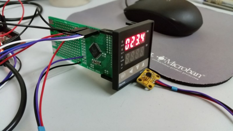
[Harvs] hacked a cheap PID controller he found on eBay to improve its performance. The controller originally used a K-type thermocouple but lacked cold junction compensation. As thermocouples only provide a differential measurement between the measurement junction and cold junction, this meant the controller was assuming the cold junction was at room temperature, and would in many cases be significantly inaccurate. The system also used a no-name brand Chinese microcontroller making firmware hacks impractical.
[Harvs] decided that even with cold junction compensation a K-type thermocouple wasn’t ideal for his application anyway, and designed a replacement PCB to interface to the display and power supply. The new PCB is based around a Cypress PsoC (a popular choice for its great analog functionality) with a DS18B20 temperature sensor. At the lower temperature ranges [Harvs] is interested in the DS18B20 is far more accurate and easy to use than the thermocouple.
Though the project hasn’t been updated recently, [Harvs] was planning on adding an ESP8266 for remote monitoring and control. Great work [Harvs]!
Thanks to Peter for the tip.


Y u no Pt100? :^)
That’s what I was about to ask!
Many of us aren’t familiar with PIDs and measurement probe types, but would like to.
Please can u explain PT 100 or k-type as it applies to these industrial PIDs?
Thanks.
Isn’t that some platinum thing? I remember a NurdRage video about it. I guess you can get some from the internet for like 5$ or less. Maybe have some glass around it?
NurdRage did that all wrong. The idea is to have something thermally conductive but nonreactive protect it.
Get some thin-walled PTFE tubing and heat the end until it goes clear, then pinch it closed with pliers, test for leaks by blowing air into the other end while it’s under water.
Thermocouples rely on Seebeck effect where 2 different metals produce a small voltage depending on temperature at the junction. They come in various types with various suitable temperature ranges. K-type is good for -200 – 1300ish C. Some others like B-type are good to about 1800C.
Pros: Fast response for bonded type, k-type is cheap, very wide operating temperatures.
Cons: Require cold-junction compensation (the connection back at the meter creates another thermocouple between metals and that needs to be compensated for), tiny voltages mean they are susceptible to noise, can be irreversibly damaged over time by metal contamination and for ones made with ferrous materials by heating above the Currie point.
PT100s are a form of Resistive Temperature Device. The common PT100 is made with platinum and the temperature is read by reading the resistance of the device.
Pros: Very accurate, very repeatable.
Cons: Low usable temperature range (up to around 600C max), slower response time than thermocouples, resistance of cable requires compensation or the device will have an offset so for any probe more than a few meters from the measuring device you need a 3 core or even 4 core cable for cable compensation if you want highly accurate results.
PIDs are control loops and I suck at explaining how it works. Suffice to say that the control loop can be tuned to use either thermocouples or PT100s, and when tuning the control loop care must be taken that the speed of operation isn’t greater than the speed of the system or it becomes unstable (i.e. control output overshoots or oscillates).
*ugh, accidentally pressed report comment while replying, please ignore report!*
—–
PT100, PT1000 and similar are usually measured with a wheatstone bridge.
using a 3 wire pt element you can eliminate the lead resistance issue by using one pair for the bridge and the third for reading.
the resistance in the wires for the bridge will cancel each other out as it is a voltage divider.
effectively reading before the resistance of one lead, and after the other.
the resistance in the third wire is negligible as the input of the controller is certainly high impedance.
they are not perfectly linear, however.
I’ve seen analog compensation for this, but today its most certainly done in code.
Please draw this up and post a circuit?
no need.
http://www.ni.com/cms/images/devzone/tut/a/a28b553b1071.gif
the wheatstone bridge produces a potential difference between the know voltage divider(r1 and r2)
and the unknown(r3 and and the element)
In a pt100 setup these could all be 100omhs so you’d have 0V at 0 degrees C.
as the temp increases it will increase in resistance and a voltage proportional to the temperature will appear.
likewise the temperature can go below 0 C and produce a negative voltage.
lead resistance is symbolized by Rl1, Rl2 and Rl3
Rl1 and Rl3 supplies the current and will have a voltage drop as the lead length increases, these will cancel out at the measurement is taken between them.
effectively Rl1 is added to Rg(the pt100 element) and Rl3 is added to R3.
Rl2 is the return for the potential. running next to no current, its resistance is negligible.
https://en.wikipedia.org/wiki/Wheatstone_bridge
Thanks Garbs, very informative.
Ah yes, another instance of jacking up the logo and sliding a new machine underneath it.
Well, sometimes you just can’t salvage everything. But atleast some part of it was salvaged and put to good use. Sure it’d be a much better hack, if he had hacked the no name microcontroller and fixed the program, but come on, it’s a temp controller.
Why not just use a MAX6675 in the first place and keep the K-type?
DS1820 don’t need compensation.
So after all, this is jus a display hack!?
More than hacking…swapping…he’s just using some bits of the original…XD
Practically all of these knock-off PID controllers run a similar firmware. It took me more than a few google searches to find different datasheets for these until I found one with enough English to detail how to take the unit into a configuration mode. This allowed me to configure the input type (Pt100, when I bought a supposed k-type only unit), as well as junction compensation, linear offsets, PID fine-tuning, reverse/normal PID process control, etc, etc.
I’m sure the original board could’ve been made to work satisfactorily if some more time was spent investigating.
Could you, please, share your findings?
Perhaps I’m not the only one having this controller at home.
Google REX-100.
(Y’know, like what’s probably written on the box.)
Even if you do find the manual, there’s no guarantee that the feature exists, or if it exists it even works. One I have lets you change the readout from Celcius toFahrenheit, but reverts to Celcius.
Shrug, YMMV and all that.
Of more interest is that sometimes the feature exists in the firmware, but the hardware wasn’t fitted – Alarm 2 output is a good example. Only takes a few SMD components… (That’s so lame a ‘hack’ it’s Had-It’s-Day worthy.)
Well a link to your super sleuth findings would be nice.
http://www.rkcinst.com/english/pdf_manual/imnzc21e1.pdf
(now on the first google results page for “REX-100 datasheet”, I think many eBay listings link to knock-off/old datasheets and thus flood the results pages)
I found this one to be pretty informative for all of the eBay REX-100 knock-offs. The information on the initialisation mode is quite handy. For some units, the unlock code is “1111” or “0000” or “1000”.
There’s also this open source PID: http://hackaday.com/2012/01/05/ospid-the-open-source-pid-controller/
Sheesh. If you need a decent controller, just go to AutomationDirect.com and get yourself one.
If you need a decent controller, just study a little control theory and design a control loop to fit exactly what you’re doing.
Eh, $10 on eBay and get on with life…
That said, a cheap on that does banding would be nice.
Much as I like to build stuff, building absolutely everything is not practical. Sometimes it’s a lot better to let someone else do the legwork and just buy a decent, properly working device. Why reinvent the wheel?
The chinese microcontroller is a STC one. These are normal 8051 cores with some peripherals. They are very cheap.
http://www.stcmicro.com/index.html
The programming tool only works on windows, but there is this opensource program: https://github.com/nekromant/stcdude