This hacker’s video on blinking LEDs never got the recognition it deserves. At the time of writing clocking in at just 61 views, but it is indeed a work of art. Just trust me, scroll to the bottom of the article and watch it, you wont be disappointed.
Not convinced? OK, let me tell you about it and the world it has opened up in the Japanese maker scene. We’ve all blinked an LED. Maybe it was just to test a microcontroller, like the simplest Arduino example.

Or we’ve been a tad more old school and used the classic 555 to do it. Or maybe like me, you went through a phase of hacking together Phase Shift and other oscillators because well… it’s fun!
But [Junichi AKITA] has more extreme tastes, deciding that a custom IC layout is the way to go. [Junichi] designed a ring oscillator composed of flip-flops, then hand laid out each MOSFET placing each layer exactly where it should be fabricated.
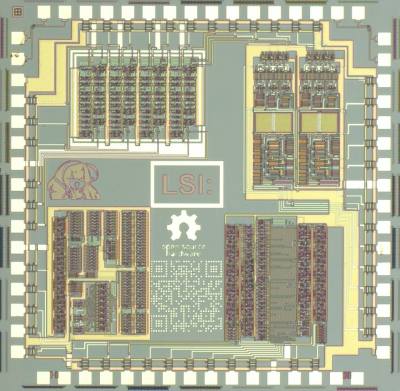
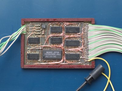
The resulting design was then fabricated by an academic shuttle service in Japan (a bit like the well known MOSIS service). The result is a tiny circuit in the top right corner of the IC. Which of course [Junichi] then had to wirebond (check the video for a cool 1980s style Westbond machine which are still hugely popular in Japan).

IC Layout… by hand!

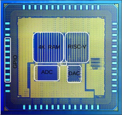
Optical image of the fabricated circuit.
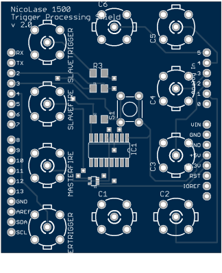
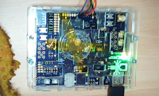
[Junichi] bonded the die directly to a PCB (COB). I assume, purely for irony, a 555, and ATtiny based oscillator were also laid out on the board.
 I guess you might have a couple of lingering questions. First you’ll likely bemoan your lack of your own fabrication facility (I’m still eyeing those used 1 micron fab lines that crop up on eBay from time to time). And secondly you might be asking yourself… why?
Both these questions are somewhat answers by the MakeLSI project. This growing project in Japan seems to have opened up semiconductor fabrication to all kinds of projects.
While my Japanese isn’t good enough to fully understand what’s happening it’s clear there are many awesome projects going on. Including joys such as IC layouts designed in vector graphics packages (Inkscape) and die images packed with interesting layouts, anime characters and QR codes.
For more awesome images and information (unfortunately all in Japanese) you can check them out on Facebook or on their homepage.
Continue reading “Blinking An LED – Extreme Edition” →
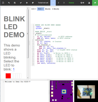 You can now program the Open-V on the web, and see the results in real time. The code is compiled in the web IDE and then flashed to a microcontroller which is connected to a live YouTube live stream. It’s pretty neat to flash firmware on a microcontroller thousands of miles away and see the development board blink in response.


 [whitequark] has been experimenting with a