A friend from the newly founded Yeovil Hackerspace introduced me to a device known as “The Kraakdoos” or cracklebox.
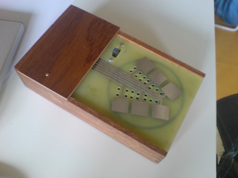
The cracklebox is an early electronic instrument produced by STEIM in the 1970s. The instrument consists of a single PCB with a number of copper pads exposed on one side. The player touches the pads and the instrument emits… sounds which can perhaps best be described as squeeze and squeals.
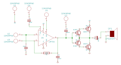
While the cracklebox was original sold as a complete instrument, the device has been reverse engineered, and the schematic documented. What lies inside is quite fascinating.
The heart of the cracklebox is an ancient opamp, the LM709. The LM709 is the predecessor to the famous LM741. Unlike the 741 the 709 had no internal frequency compensation. Frequency compensation is used to intentionally limit the bandwidth of an opamp. As input frequency increases, the phase shift of the opamp also increases. This can result in undesirable oscillation, as the feedback network forms an unintentional phase-shift oscillator.
Most modern opamps have internal frequency compensation, but the 709 doesn’t. Let’s see how this is used in the cracklebox:
 Rather than using the frequency compensation pins as intended the cracklebox just routes them out to pads. In fact the cracklebox routes almost all the pins on the opamp out to pads, including the inverting and non-inverting inputs. A single 1MOhm feedback resistor is used in a non-inverting configuration. However reports suggest the instrument can work without a feedback resistor at all!
The exact operational details of the instrument are therefore a slight mystery. However what’s clear is that without any frequency compensation the opamp is likely operating as a phase-shift oscillator. The output of the opamp goes to a push-pull output stage. This configuration is often used for efficiency. However as the transistors do not operate below 0.7 volts there is also a dead band, this results in a distorted signal in the cracklebox and also filters out low level background signals.
While it’s interesting to investigate the cracklebox design, it’s creation likely involved a lot of circuit bending, playing with component values and layout until the circuit sounded “cool” rather than adhering to any design rules. As such the cracklebox is an interesting confluence of circuit design as engineering and art.


http://www.crackle.org/index.php – Info on the Cracklebox and Michael Waisvisz, it’s designer.
http://www.steim.org – STEIM is still alive and well.
It’s nice to know there’s a hacker space down this way.
What is that magician doing to Donald Duck?
Is that the song of his people?
I believe it’s their National Anthem.
T.I.L. that there are op amps even worse that the 741
“Unlike the 741 was 709…”
?
Can i used 741 ??
I used it using big threaded pins so I could touch them and/or insert other electronic components between pads (mainly caps) and/or attach cables to the pads. Interesting inserting a cable in the ground and another one wrapped to a metallic watering can and control the sound with the water flux, for instance. I also used different type of stones and minerals, plants, etc. Delightful. Best, Fernando
I missed this post when I put mine together about 18 months ago, so without knowing that explanation on the output amplifier I’d just shoved an LM386 in there. I should rebuild the thing in light of that.
I built mine on stripboard, so for touch pads I used a set of brass standoffs — the sort that slide into a keyhole slot in sheet metal. They end up looking like strange alien flanged knobs, which is kind of a bonus. I put up pictures and slight documentation at https://taperwolf.tumblr.com/post/645507779612868608/ .
The schematic shown is wrong. The output obviously shouldn’t be connected to a grounded capacitor