
Bringing old things back to life holds a great sense of joy for most people. The never ending pursuit of recapturing our youth leads us down roads we’ve long forgotten. Along the way, we tend to bump into forgotten memories which jostle other forgotten memories which allows us to relive happy times we haven’t thought of in years, sometimes even decades. For some, the roar of a 351 small block sweeps them back to high school and the fast nights of cruising down main street with the FM radio cranked up as high as it would go. For those of us who were born in the 80’s and 90’s, video games can bring back such memories. Who among us can forget our first encounter with Link, the elegant theme music of Final Fantasy or up-up-down-down-left-right-left-right-b-a-select-start?
Advances in processor technology has allowed us to relive our favorite games via emulators – programs that emulate processors of older computers. The games are ‘dumped’ from the ROM chips (where they are stored) into files. These game files can then be loaded into the emulator program, which allows you to play the game as if you were playing it on the original system.

Technology is truly a beautiful thing. It allows us to move forward, allows us to do today that which was not possible yesterday. There are a few cases, however, where this paradigm does not hold true. One of these has to do with the Nintendo Entertainment System and its “Zapper” gun controller. The NES was the most popular game console of its time, and rightfully so. From the minds of Nintendo engineers, programmers and audio experts came some of the best video games ever made. Unfortunately, some of these great games cannot be played on your Raspberry Pi favorite emulator due to the incompatibility of the Zapper gun and modern digital monitors. None of us can forget the fun that Duckhunt brought. The game came as standard issue with all NES systems, so we’ve all played it. But its nostalgia is currently entombed by a technological quirk that has yet to be solved.
From one hacker to another – this can no longer be tolerated. First, we’re going to learn how the Zapper works and why it doesn’t work with digital displays. Then we’re going to fix it.
The Problem
The Zapper gun is basically a photodiode and a switch. When the trigger (switch) is pulled, the NES does something to the screen to determine where the gun is pointed. What this something is will be discussed in a bit. But first, we must understand that it only works on a CRT analog television. Plug your emulator setup into one of these, and you will have no issues. The problem is that nobody has CRT televisions anymore. Everyone has digital flat screen televisions and monitors. Plug your setup into one of these, and it doesn’t work. We need to understand why this is.
Putting A Myth to Rest
There seems to be a lot of confusion about how the NES knows where the Zapper is pointed on the screen, even among electronic types who should know better. Some people seem to think, and continue to put forth the myth, that the NES looks at the scan lines on the CRT. A CRT draws scan lines from the top of the screen to the bottom in a certain time interval. By looking at the time between the start of a scan and the time the Zapper sees the scan, the NES can know where the Zapper is pointed. And because a digital monitor will show all scan lines simultaneously, there is no way for it to calculate where the Zapper is pointed. This might be true of some other types of photodiode based guns, but it is not how the NES works. Not even close.
How the NES Zapper Works
It’s pretty clever, actually. When the trigger is pulled, the NES will write a blank, solid black frame to the TV (more on this later). The NES outputs at 60 frames per second, so a single frame will last 0.0166 seconds or roughly 16ms. The next frame will put a white rectangular box around the target duck, with the background remaining black. At the same time, it polls the state of the photodiode in the Zapper. There is a measurable difference in the output of the photodiode when pointed at a black part of the screen versus the white box. And this all happens in only two frames, or ~32ms. You can barely notice it. The following frame goes back to the game and records your shot as a hit or miss. Brilliant!
“But wait, how does it work when there are two targets?” Good question. The NES engineers dealt with this issue by doing the exact same thing, just twice. So you would get the solid black frame, then the next frame would paint a white box over one target and poll the photodiode, just like if there was only one target. If there is another target, the third frame will just put the white box over the second target. The three frames happen in about half a second, so you don’t have time to shoot both. You can only shoot one, and this technique allows the NES to know which one you shot.
“If the NES is just looking at the state of the photodiode, can I just point my gun at a bright light and score a hit every time?” This is another good question. The NES engineers took this cheat away by first writing a black screen and looking at the state of the photodiode, ensuring this would not be allowed. If it sees anything other than the black screen, it will record the shot as a miss. It is rumored that some very early versions of the game might not have had this bug fixed, but there has been no demonstration of such a bug to date.
Another Look At The Problem
Now that we know how the Zapper actually works, we can move on to a resolution for the digital monitor issue. If 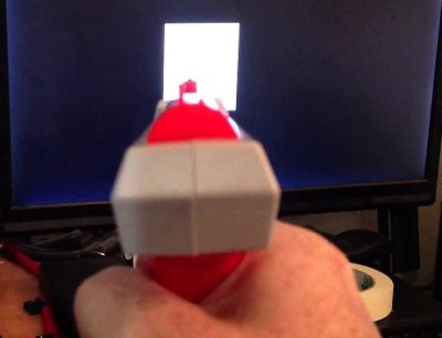 all it’s looking at is the white/black contrast, it should work just fine on a digital monitor. But it obviously doesn’t. There are some that say the photodiode is sensitive to IR from the CRT, and a digital monitor does not give off any IR. But take a look at this 12 second video. The zapper seems to work just fine!
We know the scan line argument is rubbish and the Zapper can discern the white/black contrast on a digital screen. We can only conclude that our issue is timing related. It appears that an analog CRT can write an image to the screen much faster than its digital counterpart. The NES is hardcoded to look for the white box after 16ms has elapsed. If our digital screen is unable to process the output of the NES fast enough, it will be looking for a white box while the normal game screen is showing.
The output resolution of the NES is 256 x 240. A digital monitor would have to process each frame to scale it up to its set resolution. This process introduces a lag which can reach up to 70 ms, well beyond our 16ms frame rate.
How To Fix It
Well, it won’t be easy. If a digital monitor is, by its nature, too slow, the only resolution is to slow down the NES.
Option 1 – Underclocking
We’ve all heard about overclocking. But what about underclocking? Could we slow down time in the NES processor without accelerating it to a percentage of light speed? It would have to be done without locking it up of course. It would need to run at normal speed, but when the trigger is depressed, we would need to switch over to a lower clock speed and effectively lengthen the delay times. Remember, the NES writes a black screen, delays for 16 ms, and writes the white box. By slowing down the processor, we can lengthen that delay and give the digital monitor time to catch up.
Option 2 – Edit the ROM
The only real way to edit a ROM is with a hex editor. What if we could single step an emulator and find the piece of data that represents the delay after the trigger is pulled? If we could find it, we could just make it longer and hope it doesn’t break anything.
Option 3 – Your Turn
Now that you know exactly how the NES Zapper works, and exactly why it can not work with a modern digital monitor, you are well on your way to solving the problem and freeing the nostalgia that a cruel twist of technological fate has locked away from our generation. What would you do to make the Zapper work with a digital monitor and become an instant internet hero?
This is not a complicated setup. Surely we can put our heads together and get the Zapper to stop firing blanks at our digital world. Let us know your solution to this problem in the comments below.


what about an external upscaler? something that would use the HDMI input, which, in teory, should be faster?
The external upscaler still introduces lag as it processes the signal.
Would that work with just the 10$ ones?
Some TV’s have a something called game mode. It reduces lag by minimizing the video processing it does to the signal, sacrificing video quality for speed. In this mode the signal processing delay is reduced to under 5 ms. There have been reports of people being able to play duck hunt on certain TVs, several years ago I stumbled onto a form that had a list of LCD TVs where Duck hunt was playable in game mode, which I can’t seem to find now. Although I’m not sure how playable Duck Hunt was, this is still a lot of delay. I imagine this delay makes it harder to play especially as ducks get faster.
I do not see any mention of the fact that the light gun is looking for light modulated at 15.7 kHz (USA freq.). This is the horizontal line redraw rate. That is why it does not work with an LCD monitor. The zapper is not looking at the square as a whole … it is looking at each line in the square making a 15.7 kHz modulated signal. This way normal lights in the room do not trigger it. To test just take a zapper … hook the data line up to a scope and the power up to 5v and ground. Modulate a led with 15.7 kHz with your favorite micro. Point gun at led and pull trigger. Observe data line. Now just turn the LED on solid no modulation. Observe data line. I used one of these gun circuits in a laser harp application where the laser beam was modulated at 15kHz. It worked well other than the narrow viewing angle of the photo diode on the gun.
But they link a 12 second video that shows the zapper does in fact work with a LCD monitor. It just doesn’t work when playing the game.
The gun in the video is not original, see comments: “I redesigned the light sensor in the gun”.
That may be because of the backlight inverter running at some high frequency that the gun picks up. This is not a universal case.
Proof is in the pudding, or in this case youtube’s comments:
“I redesigned the light sensor in the gun and also had this hooked up to an FPGA which is driving the LCD display and also used for the trigger event. ”
So the gun itself is modified to work with an LCD. It isn’t looking for some specific modulation anymore – which means it’s possible, but it’s no longer possible to determine whether the gun is looking at the screen or some other blinking light.
fair enough. i wonder what the preceding black screen during game when firing is for. I can’t imagine it would all be an effort to keep people from cheating. would be pretty impressive if it was though.
It needs a rising edge, or a full high-low-high to generate the signal for some reason. Otherwise the game could just look for a logical high and then draw a black box on the duck to see if the signal drops.
My guess is that it has something to do with human persistence of vision. We might notice the black or white square flashing in, but not if the entire screen blinks.
Or, it might do with the afterglow of a CRT. They might have needed more contrast to reliably detect the flash.
“That way normal lights in the room do not trigger it” BS. I grew up in that era. We had florescent lights. You could point straight up at the light and the gun would count it as a hit, it was a very reliable method to cheat.
Cool hack? There is no hack. The article asks us to figure out a solution.
The most cost- and time-effective solution for me was to just get a CRT, and plug my NES into it. Seriously, nobody uses CRTs anymore, but there’s millions of them out there. I have a friend who wanted to get rid of one, and before he actually brought it over, I got another from a neighbor. Both free. I have the NES plugged into one, and the other is, I guess, my emergency backup. You know, in case the first one fails and I REALLY NEED to play Wild Gunman. Also, my first HDTV was a 34″ 1080i CRT that weighed about 100 lbs., and was about the size of a compact car. I should have kept that beast. It’s the best of both worlds!
Is it just me or does it not bnother anyone else that he got the Konami code wrong?
You’re not alone…
*sigh* when will humanity learn?
Bothered the hell out of me! ;-)
Damnit. I even googled that. Fixed and thanks!
As long as you don’t mind those of us that dislike calling a 351 engine block ‘small’.
GM 350, Ford 351W, Mopar 318, AMC 304, all are “small” block engines because they were significantly lighter weight designs made with the latest casting technology of the 1960s. The previous engines used by those four major American makes were physically larger and heavier.
Then there were the big block engines, different designs from the small blocks and mostly 400+ cubic inches swept displacement. AMC didn’t have a big block, they just opened up the 304 to 401. GM also made a 400CI version of their 350. Ford upped the 289 to 302 by lengthening the stroke then to 351 by increasing the deck height and widening the intake manifold.
The aftermarket of course went even wilder with stroker kits to push a Ford 302 or GM 350 to 380+ A problem with those is the pistons get real short and correct clearances are very important to keep the pistons straight. I know there are stroker kits for the 351W, dunno how big those can go.
Continuing the one-upmanship in small block V8 engines, GM offers a 500 cubic inch LS1, which unlike Ford and Mopar current products still has a direct lineage to the 1960’s. In 2008 Sonny’s Racing Engines was somehow stuffing 524ci displacement into the GM small block package.
Of course none of these are available in production vehicles and California says they’re only legal for off-road use or in vehicles made before their emissions laws were passed. (Or in “one ton” trucks made into the 1980s which were still exempt from emissions laws.)
Dude… you really are a nitpicker. Relax.
What about adding a physical delay on the trigger of the zapper?
Seems the best bet, should be adjustable though as LCDs might differ.
Doesn’t the trigger on the zapper tell the software when to run the targeting routine?
http://vignette4.wikia.nocookie.net/contra/images/5/58/Moses_Contra_code.png
you can raid the landfills for the next 10 years for working or repairable CRT TVs… has anyone tried the Framemeister with this? It’ll at least get the lag down to a more manageable level (but probably won’t fix the situation either). Oh I just read the Framemeister takes 24ms.
Hmm I think I have an Idea: The NES PPU (Graphics Chip) fires an NMI each frame. Most games use this as the internal clock (perform calculations, wait for next frame). So if you pull the trigger on the Zapper, you must swallow every second NMI to prevent it from reaching the CPU (could be done with a few logic gates). Since the PPU buffers the picture, that could just work. So yes basically this is underclocking, but without gamebreaking side-effects.
Note this only works if the Zapper LDR state is buffered, as in the CPU asks a circuit “has the LDR reported ON or OFF the last frame?”
If it works, it will extend the range to 32ms, within the Framemeister timings. Newer TVs should support Ultra Game Mode…
(if the LDR is polled or the CPU sets its IRQ, it won’t work)
Or this workaround:
* Put a WiiMote sensor in the Zapper
* Re-code your emulator to return the pixel intensity of your WiiZapper’s aim each frame
* Profit?
Yep, this is what I came to comments to say. Use a wiimote. They make pistol adapters for the wiimote, or 3D print yourself something that looks similar to the Zapper and put the wiimote inside.
Have hacked Wii with NES emulator. Have NES Zapper. Wish to subscribe to your newsletter.
Yep, this works. Done it for fun (Wiimote + gun adapter), although, not in a NES emulator but on a Duck hunt clone written in Python.
This will help, no doubt…
http://www.google.com/patents/US4813682
On a side note: it seems the NES dosent’t have the logic to get an approximative x/y position from the gun pointing at a white screen (pixel counter latch), but the Sega Master System does. I haven’t heard of any Master System game which uses the white squares method.
I remember reading that *some* high-def TVs will work with the Zapper (Probably depends on whether the TV scales the video or not, or otherwise how much the signal is processed in the TV) but that none of them will work with the SNES version of the Zapper (Super Scope?) because that one actually used a calculation with the scan lines in the TV to determine position , and since scan lines don’t exist on the LCD/DLP/Plasma displays, it won’t work at all.
I am scratching my head over the statement the CRT was faster… CRTs, if you lose power, still glow for a good 30+ seconds later. This is due to the phosphorus still being partially excited. Therefore, even if the refresh was faster (most monitors and screens were not that high end if they were attached to a NES), the still partially glowing phosphorus would blur the image. Whereas most LCD screens can handle 60, 70, 90 Hz.
However, a screen that was not truly black could be used. LCDs, while not truly black either, do not show the ghost image, only the backlight, which is not as bright as the white box. Whereas the CRT still had the ghost image, so the black was more of a dark color. Basically the lower bound for the contrast needs to adjusted. I bet if the GPU was used to ghost the image (or not truly black the screen), and the scaling timing issue was address, it would resolve a lot.
It doesn’t matter how long it takes to turn OFF the screen. It matters how long it takes to turn ON the screen. An LCD TV usually goes like this: Wait for a frame to be completed, do some processing to make it look less ugly (and usually failing at that), putting the frame on the screen. A CRT starts putting the frame on screen the very instant the first pixel is transmitted. As the video signal controls the Cathode Ray’s Intensity in REAL TIME.
Why not modify the controller to trigger the shot sequence twice? The second shot is triggered when the blocks are shown on the screen from the first shot. You could calibrate the delay for your particular setup once, and in theory it would always work from then on. (Monostable 555 + trimpot anyone?) If I’m reading the numbers correctly, we’re talking about a ~70ms delay between shots. Unless there’s a lockout or delay period to prevent rapid trigger pulls of course.
The code running in the NES requires that it see the light from the square the exact same vblank that it’s drawing the square. If the TV adds more than 16ms of latency, there’s no way for the code running in the NES to know that the zapper would have seen light.
Well my thought was that the second sample from the zapper would see the first square. Whatever latency in the TV would be accounted for by the time between the first zapper triggering and the second zapper sample. After a few hours of deep introspection (or just rereading my response), I remembered it’s one shot per duck, so this idea would require recoding anyway.
So here’s my stab at OG gamer cred…
When was about 2 or so, my dad and uncles had a Magnavox Odyssey game system. Not the Odyssey 2, the ORIGINAL Odysseus. The one with the screen overlays and etch-a-sketch style controllers. Anyway, it came with a light gun. That light gun was terrible and I vaguely remember seeing my dad point the gun at a lightbulb and rapidly pulling the trigger. He remembers that gun could be fooled by that same trick.
Can anyone else verify the claim?
You can play duck hunt via an emulator on a hacked Wii with the wiimote.
The 351CJ was the One that all of the Mustang boys wanted. I’ll give you that 92% of the 351 were low powered C’s. Folks always wax nostalgic about their 351 Clevelands like they were the best thing around…. Were they really? that’s up for debate, but some folks have a soft spot for them all the same.
Even though Duck Hunt uses marching bounding boxes to detect where the zapper is pointing, some later games actually determine the Y coordinate by raster timing, such as Strike Wolf or Damian Yerrick’s calibration/characterization program Zap Ruder.
Just to make the problem harder.
Presuming
1) there is no “frequency detect” (Which I would have doubts about given PAL versions and the imprecise clock speed changes entailed);
2) the timing issue is due to HDMI / LCD transmission and decoding lag, and simply using analog output doesn’t fix it
3) we don’t want to just cheat
4) it doesn’t require a black screen AFTER registering a hit
Suggestion 1)
Blank the photodiode output for 16ms whenever you pull the trigger. There may be enough leeway in the code that a hit would still register (or potentially you’d hit the second target instead).
The result may be that you always hit, as you will still be pointing at the hunting scene render when the program thinks you are pointing at a target box.
Suggestion 2)
Short of reducing output lag as much as possible between the graphics card and the monitor (use VGA out, no AV boxes, etc. ) I suspect that a timing hack (interrupt the flyer a emulator after going through a screen-blank sequence, then repeat the sequence after a lag adjustment)
E.G.
Native timing
Output: –?ms–Blank–16ms–Target1–16ms–Target2–16ms–SceenRender
Input: Click–?ms–Low—-16ms–High——16ms–Low——-16ms–SceenRender
LCD timing
Output: –?ms–Blank–16ms–Target1–16ms–Target2–16ms–SceneRender
LCD: : Scene–70+ms——————————————–?ms–Blank–16ms–Target1–16ms–Target2–16ms–SceneRender
Input: Click–High–70ms—————————————?ms–Low—16ms–High…
LCD timing with interrupt
Output: –?ms–Blank–Target1–Target2–SceneRender–70ms–INTERRUPT–Blank–16ms–Target1–16ms–Target2–16ms–SceneRender
LCD: : Scene–70+ms——————————————————————-?ms–Blank–16ms–Target1–16ms–Target2–16ms–SceneRender
Input: Click–High–70ms————————————————————–?ms–Low—16ms–High…
You’d get jitter as it “replays” the output
The interrupt could be on receiving the click, save the state, then replay from that state after screen lag is accounted for.
Or just pause the game for 70ms every time the trigger is pulled…
Ok so since this is the future, what about using CV to recognize the duck *before* the trigger is pulled? If the camera detects the duck before the trigger is pulled, once you do pull you could send a spoofed “white square detected” signal (which I presume is 0xFF) down the wire.
It might require some funky optics, but there’s plenty of room inside the zapper itself.
In my opinion, this is the best answer. Detect a duck, say “you are winner” to the NES. Done.
The clever thing here is the *before*, and it needs to be enough before for CV to do it’s work too. This side steps all the white block issues, including the need to defeat or emulate CRT modulation filtering. What I can’t work out is how you’d get this method to resolve multiple simultaneous targets.
*before* wouldn’t be a big deal if the CV was continuously scanning for the duck sprite, or depending on the camera’s FOV, parts of the sprite. Depending on the optics, you may have to keep the gun at a certain distance to ensure that the camera is in focus.
It wouldn’t have to be multiple simultaneous targets, as the gun will only be pointed at one target at a time (as I recall, if the birds fly over top of each other, you still have to shoot twice, and one sprite will be in front of the other).
So you’re still only looking for one sprite at a time. There are twelve possible sprites to look for (there are six “in flight” sprites, *2 because they can be mirrored to fly left or right. The other bird sprites are of the bird flying off screen or after being shot). There are different colours for the birds, but that can probably be resolved by doing the CV in grayscale rather than colour, if there are speed issues:
https://www.google.ca/search?q=nes+duck+hunt+sprite&espv=2&biw=1745&bih=861&source=lnms&tbm=isch&sa=X&ved=0CAYQ_AUoAWoVChMIxcO-jPiXyQIVCiYeCh1ZuQQw#imgrc=wAkO2wte6gkuhM%3A
Since the sprites are really simple bitmaps (no shading, no round edges), it seems pretty easy. But I say that having never done any CV work myself :)
Good idea. How do you know which duck you are pointed at? Would the camera see the whole screen and then take center screen for the gun aim. might work. but then how do you know when to send the FF down the line? Would need to know how the game does the white blanks. duck on top first or duck 1 then 2. but only the game knows which one its testing for. could just kill a duck. 50% chance the right one dies. :)
Ooh yeah, great point! I think you just blew up my idea, but there might be some clever work-arounds if we knew which duck was which when the round starts…sounds like we need even more CV!
Needs more CV
Since the delays exist. Could rom coded be modified to add a blue box for the second duck and a second sum check black screen before it.
This overs multiple ducks and single ducky.
For single ducks, black screen, white box times two, Nes says only one white box “counts” so second blacks teen/white box is just for time delay and consists within the ms delays. When two ducks are out the second screen/white box is a “blue screen/white box” Nintendo has necessary delay in time AND an improvement, the SLIGHT possibility of A TWO duck hit, one on a black background, one on the blue background, yet the two correct shots would just be an unusually fast player that reached the possibility, so a game that doesn’t exclude that I the code because they fell physics would exlinate the possibility, so it was left open, possibly in jest. We only want to build in a nominal delay to still play nice with hard coded timing, that that and flexible scenarios due to the uniformity of tvs in the 80’s and a humble projection of the products life expectancy was unlikely to need future systems flexability. Also nintendos desire for a loose but existent programmed and desig obsolescence. What about plasma tv’s? Can they produce a along fast timings? There are fewer of them, but OLED/OLED plus prioprietary tech tech to reduse blur like a plasma. 45% screens with different refractory angles and therefore ranges or lost packets while testing them wit the laser. So many variable to work on all screens. Newer models with half and or variable pixel intensity to replicate that plasma on/off performance. 4K tv handling much more data, would require even more compensatory delay in yet another variable. What about 8K? Not for us but for Nintendo, Japan still wants 8K to be long term standard, and is locally using it to remind others it exists and they want a relevant console gain, amazing intuitive tech became the wiimote, did someone ask for a new gun with wiimote internals? Might they say… “Looks like this. ;)” low tech what about a a black and white card slotted into the gun, that appear in front of the diode the are slid away so it sees the normal screen. As in always give it what it needs to see every 16mn by slides, ech different, like the viewer we had as kids with slides of picks on. Disc. Gun sees slides, we see the tv screen. Seems flawlessly timed in the bigger picture. You could slow/speed up the disc buy gearing and or adding/removing slides.
Advances in processor technology **have** allowed us to relive our favorite games via emulators
I hate to break it to you, but the “The NES outputs at 60 frames per second, so a single frame will last 0.0166 seconds or roughly 16ms” is entirely incorrect. NTSC video is 30 frames a second and 60 FIELDS a second. A field is half the scan lines interlaced. In order to paint a completely black screen, you need at least 2 fields to scan – 33ms. You could pick up white with only one field, but the gun can distinguish that. So you would need two fields to completely erase one box and draw another. Otherwise you could have a false positive. Your calculations need to be revised for 30 fps, not 60.
You are right, 30 full frames, but the frames are interlaced, so it boils down to the correct terms.
That said. It’s not 30 or 60. NTSC ‘Framerate’ is 29.97 Frames Per Second.
The community has hacked about Super Mario World, is it really so hard to find the code responsible for the black screen and white text?
*IF* the trigger can be triggered twice in quick succession, then a simple delay to ‘double-tap’ the trigger will resolve the issue. Otherwise I don’t see any external hardware that can be used to solve this puzzle. You will need to modify the ROM, or modify the hardware it is running on.
The NES and many other consoles render in 240p though, not 480i. You’re probably right that it renders multiple fields so that a 480i TV will blank the screen appropriately, and that 33.3ms is probably more likely (I’m sure this can be checked quite easily).
It was entirely correct, a single frame in the GPU or on an analog TV from the NES would be 0.0166 seconds. The NES outputted modified NTSC where every field was in the same location (all odd scanlines or even, instead of odd, even, odd, even) and every field could be totally different (60fps). So a single frame could fully blacken the screen.
Replace the photodiode with a small camera and use open cv to look for the duck. Screw those squares!
What if you fire the trigger 2 times in rapid succession. with an appropriate offset.. so if the lag is 40ms, you fire the gun 1 time, then 40ms later. This way you trigger the screen events 2 times. so you check for the first set of white squares during the second display?
That’s not going to get you a high score – half your shots will ‘miss’.
The problem is with the Analog to Digital conversion, every single one of the professional scaling equipment I have used as a broadcast engineer has been a minimum of a frame of delay, and that’s before you start putting in signal processing like comb-filters and the like.
Sure there are plenty of sub-field speed digital scalers out there (most settle for sub frame), but because the signal data is packetised it needs a whole frame to encode before it can shoot it up into the digital domain.
The biggest challenge to this is the front end found on every display for the consumer market, this is *possibly* doable with a custom driver board that is happy to drop a lot of the processing that goes on with getting stuff to and from standard digital video transport such as HDMI, DVI and SDI.
If you’re using an emulator, aren’t all the signals going through some kind of intermediation? So why not make a special version of the emulator that can just stretch the clock when needed? This doesn’t help the original games at all, of course.
@Will Sweatman
> “The three frames happen in about half a second, so you don’t have time to shoot both.”
3 frames @ 60 Hz = 1/20 second (.05 second), not 1/2 second (.5 second).
50ms, 500ms, is there REALLY a difference?
“The 351m was a truck engine…”
Yup, and some of us drove trucks in high school ;)
The author obviously meant the 351 Windsor, or perhaps the Boss 351 version of the 351 Cleveland, available only in the 1971 Mustang. 1,806 Boss 351 Mustangs were made, 591 of them are accounted for in the Boss 31 Registry.
What’s so special about the 351W? Torque, lots of it. Even the 2bbl carb version from 1971 has plenty. I have a stock 1971 351W in my 1977 Mustang. Coupled with the C4 transmission from the same car the engine came from, it will take off at idle, up a slight incline. No power/fuel wasting slip in the torque converter used in whatever Ford they came from!
Use an LCD that does have a much faster scan rate and build the emulator hardware to emulate the interlaced scanning of a CRT. The actual scan rate would need to be fast enough to display a series of frames that each have one more line displayed than the previous frame.
That could work for light gun systems that detect based on the scan line’s vertical position, but wouldn’t work for systems that sync to the scan rate for detecting sub-line horizontal position – in other words light pens.
To make a flat panel that normally renders whole frames at once work with a light pen would require an insanely fast refresh rate, adding one pixel per frame, possibly even emulating the very slight fade from the start of a field by the time it reaches the bottom.
Quite a paradoxical situation those engineers and programmers had, making a system able to work out a horizontal and vertical position on a screen, speedily scanned 2x per frame by an electron beam, while also having to accommodate phosphors with a slow brightness decay to make persistence work. CRTs are an odd combo of speed and slowness.
The one that looks the most promising is one of the VGA conversions: http://retrorgb.com/nesrgb.html
Combined with a low latency vga input monitor/tv. (One of the 5nS ones for gaming.)
Only the composite inputs seem to have the huge delays that cause the problems, but I can’t find the links that reference this.
That’s the path that a friend is going down, has the added advantage of being able to use the universal Nintendo connector too, to make for a neater conversion.
>The three frames happen in about half a second.
Nitpick, but 3 frames happen in 1/20 of a second, which is a little under “half.”
I’ve done some dabbling in NES programming and also worked a decent amount with video so maybe I can ring in and help dispel some of the mysteries here. :) The CPU inside of the NES isn’t capable of moving around the amount of memory required to draw the screen even at 256×240 pixels. Instead, a series of tables are generated in RAM across several frames (so there are enough CPU cycles to make them all) which tell the Picture Processing Unit (PPU) what to draw and where to draw it on the screen. Each and every frame of the output is then drawn in real-time by the PPU to the analog NTSC or PAL output depending on the country in which you live (North America and Europe use different standards). I’ll only describe NTSC below since it’ll apply in both cases.
There are several huge advantages of this approach that allowed Nintendo’s engineers to draw interactive games at high speeds with a <2MHz processor. There is one large downside though. The PPU doesn't allow for you to write its RAM contents while it's outputting data to the display to avoid contention on the memory. This is the limitation that's going to play into the answer to this question but let me describe why. It's important to note before continuing that the PPU is outputting the video to the display and generating the clock signals that drive the VSYNC and HSYNC in the CRT television.
Since the CPU can't write to the PPU RAM while the PPU is using the memory, you've got to get clever. The PPU generates the output signal that's used directly by the CRT television. Therefore, it can generate an interrupt to the main CPU at the exact same time as it starts to output the VBLANK portion of the NTSC video output. Historically VBLANK was to allow televisions to reset their electron gun to the upper-left corner of the screen every 1/60th of a second (it takes longer to go up and left than just left to the start of the next line). Nowadays this excess time is used for other features such as Closed Captioning since televisions (by design) don't output data during this dead period of the analog output signal. But I digress….
This CPU interrupt is called the Non-Maskable Interrupt (NMI) and occurs exactly at the start of each and every VBLANK period from the PPU. The duration is exactly 2273 CPU cycles (http://wiki.nesdev.com/w/index.php/The_frame_and_NMIs) and a LOT of work needs to be done. Any graphics changes that were pre-calculated and stored elsewhere in memory need to be written to the PPU as quickly as possible so that the memory will be idle when the PPU begins writing the next frame of video. Getting extra time isn't an option as the PPU has to draw data at a fixed rate to make the correct analog signal. You've got to know what you want to draw and quickly get it out there. Have too much to change in 2273 clock cycles? If you shut down the PPU output off for a complete frame you can output black and write as much as you'd like. That's why most games have a frame or two of black between a menu and "normal" operation. The graphics palettes need to be redrawn.
Where am I going with this? Let me wrap it up. There's a causal relationship going on:
1) Someone pulls the trigger
2) The CPU + PPU generates a single black frame
3) The CPU + PPU generates a target frame
4) Scoring is decided.
Pulling the trigger can be considered an asynchronous event since the player can push the button whenever they'd like. After that, there will be an exact sequence followed throughout the rest of the chain which means that the output and subsequent decision about scoring will be a synchronous relationship.
By virtue of simplicity CRT televisions are too dumb to behave otherwise. There's no memory for a frame buffer so the data has to go out the to screen immediately. Therefore, the instant the PPU says black, the TV is immediately black until the PPU says otherwise. The PPU gets to pick when this begins (because the NES has an oscillator and RAM) but the CRT is showing the video live. You can therefore consider the output to be synchronous with the PPU. Since the PPU and CPU have a synchronous relationship (by virtue of the NMI interrupt which allows for graphics updates) the CPU which makes the scoring decisions is also synchronous with the CRT video output.
LCDs are also designed for a 60+Hz refresh rate. However, the liquid crystals aren't getting polarized in the display the instant the data arrives to the display. They're getting polarized by a controller IC that is designed based on the ordering of the pixel pattern in the glass of the display. These are changed constantly and it's possible that some displays could work. But only on displays where there isn't any upscaling or anti-aliasing where the LCD is adding a frame of delay to try and make the output look better. A single frame of delay breaks step #4 listed above. Also, you can't use an adapter to get the data into the display since most adapters will digitize an entire frame of data from NTSC before attempting to output it.
Anyways, I hope this helps. If you are set on making this work your best bet will be to try and hijack some code in the NMI routine to add a fixed frame delay by stopping the game for 1-5 frames so the slower LCD can show the correct image before scoring is decided. Be careful though, as most games play every trick in the book to make the most out of the time-constrained NMI interrupt since they're the most valuable CPU cycles when any memory is free to be written.
Good Luck!
Wow, very interesting explanation! Nice to get some insights in the constraints and how they challenged it.
Thanks!
So the NES draws an empty frame before drawing the targets? Perhaps the emulator could pause the CPU when it gets a black frame?
I’ve been thinking about this some more and if I were going to try to generalize this solution to a display with a random delay (LCD as compared to CRT) I’d probably try something like the following:
1) Starting with the frame after the trigger is pressed draw the black frame as usual.
2) Sample the zapper photodiode at least twice per frame at equally-spaced points to see if the photodiode registers less light.
3) If the photodiode doesn’t get darker within 1-3 frames (TBD) then the zapper probably isn’t aimed at the screen and count it as a miss.
4) If the photodiode does get darker within 1-3 frames (TBD) then advance to showing the white targeting window for the exact next frame and act normally. You’ve re-locked to the display output so the 1 frame of delay to showing the white box will be guaranteed to work. The hit vs miss will work exactly how it was intended.
I initially thought that you could measure the screen latency with the first “shot” of the zapper but that won’t work if the display isn’t running at a multiple of 60Hz. It’d be better to do the calibration each time to make sure that computer displays at 72Hz, etc don’t alias every 5th frame and cause a 20% chance of a false miss. You could probably do the latency measurement at the start of the game if you sampled at least twice as fast as the screen refresh rate (thanks Nyquist!) but I’d have to think about it some more.
The only noticeable side effects would then be either:
1) Live recalibration: A couple of extra black frames every time the trigger is pulled (which would be annoying)
2) Fixed calibration: The ducks would appear to continue moving for a couple of extra frames after you pulled the trigger (which means the player would either have to hold their aim at the current location on the screen after the shot or continue tracking the target after pulling the trigger which is unnatural).
can you pause the CPU for several frames when the trigger is pulled?
I reckon the approach of single-stepping the emulator until the white square is drawn and then inserting a few NOPs into the code is the best bet. Play with the number of NOPs until it starts working! Does anybody know the NES HEX code for a NOP?…
One would have thought it bto be 0x00, but it isn’t. Google tells me that it’s 0xEA. http://nesdev.com/6502.txt
Ok, I got it.
take the rom, add a small calibration at the beginning of it , like “please point at the screen” and make the screen flash until you have a good “timing” for it, than store that value in a variable and use the variable instead of the hard coded timing in the game :
Profit.
Assuming that the timer lies in the zapper, i would edit the zapper to look for a black-white event for 100ms, as in check it every ms, technically you could then hit two targets at once if youd move the zapper fast enough, but at least you can hit things again.
Actually been thinking about this problem myself on and off for a few years aswell, would love to see somebody solve it.
There are many ways of “Hacking” the software and I’m sure that some will certainly reach the desired goal. But I consider that cheating, because the problem was caused by software in the first place, so what some consider “hacking” others might consider “bugfixing”.
So let’s assume the following hardware approach…
A microcontroller running at many MHz will be connected to a Wiimote optical sensor, the video output of the NES a trigger and the gun input NES. The Wii position sensor is being read constantly so this positioning information is stored in the microcontroller. I.o.w. the microcontroller knows where the gun is pointing at. This ofcourse requires a calibration before the game starts, but that is just a detail that can be solved by making the microcontroller overlaying an extra video signal to the TV. But again that is just a detail.
When the microcontroller detects that the trigger is pulled it will wait for the screen with the square in it. As soon as the position of the gun match the position of the square, the microcontroller will activate the NES input simulating the signal that normally comes from the optical sensor.
This makes the system completely independent of the TV or monitor used, because the assumed delay as mentioned in the posts above are not guaranteed and may/will vary depending on the TV monitor used.
This system can also be made to work with the lightpen based systems, because the microcontroller is directly connected to the video signal it knows the exact timing. Therefore it can fake a lightpen signal that normally comes from the coupling between a CRT and a photosensor. This is a project that takes much more effort to get it right, but when it works it can be made to work for all gun based games.
Kind regards,
Jan Derogee
If we run it on 256 x 240 resolution on a digital screen, it will not have to scale it up and won’t introduce any processing delay. Thus it might still show the frame after 16ms, right? Won’t this solve the problem.
Yes, the resolution would suck, but oh well!
Long time ago in russian galaxy…
Well. When I was young (Still I’m young), I read magazine named “Radio”. There was NES gun emulator. I soldered it, but it didn’t work. Probably because I used K155TM2 ICs (similar to 7474) instead of K561TM2 (similar to 74HC74). Probably it’s time to remove dust from my HiTex (NES clone) and do some arduino or propeller soldering…
Have a good read (with google translate)! Link: ftp://ftp.radio.ru/pub/arhiv/1998/04-98/ Pages (PDF files): 42 43 44 and 45.
Okay i didn’t see anyone post about cheating on this game. But back in the day (i think 1989-1990) me and my friend somehow figured out that if you held the gun right on the screen near the bottom you would always hit a duck. We played the game like that forever one day and the ducks where flying so fast around the screen it was some funny $#!^. I tried the same thing later in life when CRT’s where still around and i couldn’t repeat it. My friend did have an old black and white CRT tv in his room, could of been what gave us the advantage.
I do still have my original NES with Super Mario Bros, duck hunt and the World Class Track Meet game in one. That came with the power pad. but i lost the power pad and the grey gun. I did purchased the Red Zapper gun 10 years back. should pull that stuff out and build a openCV Raspberry pi controller?
Anyone else ever cheat on duck hunt? Maybe i had a version without the bug fix? I need to find it now? could be worth money.
Also cheated on the power pad. If you only used the heals of your foot you could run reallllly fast.
Sometimes cheating worked from small distance to CRT. I didn’t figured out why, and… Duck hut was boring compared with Contra, Jackal or Metal Gear. So, I can confirm that Duck Hunt cheat worked on NES cloneswith bootleg cartridges too on beginning of 90-s (1992-1995 or so).
Anyway, it’s interesting to make device who cheat NES machine by analyzing composite video signal. It shouldn’t be too hard on 21st century…
This worked for me too. I had a small (5″ diagonal or so) B/W TV; if the gun was held right against the screen, did not matter where, it would always register a hit. I could not repeat the trick on any color screen though.
As an Australian I have to get in on this OT comment to point out that here we used 351 Clevelands in muscle cars in the late 60s and 70s. XY Falcon GTHO was probably the most notable. Remember the interceptor, “the last of the V8s” in Mad Max? Phase 4? A XB Falcon Coupe with 351 Cleveland.
I admit I’ve never played an emulated game nor do I understand the exact setup, so this may be a very stupid question: is the host’s video driver buffering the display? At least double buffering is standard to prevent screen tearing when windows are dragged and such. Modern video games can disable this (‘v-sync’ I think they call it), but if the emulator doesn’t you will have an additional delay of a frame regardless of the monitor used.
I just have a few comments:
The Wiimote suggestion seems logical, but a standard off the shelf wireless mouse might be even more practical, since anybody can get one and the emulator need a standard mouse API. As a side benefit, a standard mouse would work as well.
Some mentioned using a camera + CV software to detect specific sprites for the ducks, However this approach would be difficult and unnecessarily hard coded to the game. It would be both easier and more generic just to detect where the camera is pointing by using the entire screen as a reference regardless of what’s displayed on it. Image processing would therefor output a coordinate pair for each frame and the emulator could use the information to emulate the zapper’s input. I don’t think this is the most practical option for most users, but hey it should work well.
I’m copying this from my own post on myself on the osnews website:
Perhaps there is a more novel solution for using the same detection technique as the original hardware and without fixing the ROM or “pausing” the game every shot to correct the timing.
Using an emulator, when a shot is fired, we can emulate the code paths for all hypothetical shots in parallel in the background (ie “fork” the emulation). The foreground process will display the boxes as usual but will not detect any input in time, however the forks will continue to maintain correct game state as though those shots had been taken. One frame later (or however long the LCD digital render delay is) the physical controller will capture the target boxes on the LCD and the emulator will be able to immediately select correct branch of emulation and discard the others(*).
In theory this technique could be used for arbitrary digital delays on the LCD side without touching the ROM or knowing anything about the game (although obviously the longer the gap, the greater the divergence between branches). This could be better than pausing/slowing down timers (which could impact sounds/music/graphics/etc).
Not sure if this has already been mentioned but the solution is really really simple.
You just need a buffer on the input for the NES Zapper in the Emulator. Whatever bytes are set for the IO, they need to be buffered by the same delay as the monitor. This would need to be fine tuned of course for each display.
“You just need a buffer on the input for the NES Zapper in the Emulator. Whatever bytes are set for the IO, they need to be buffered by the same delay as the monitor. This would need to be fine tuned of course for each display.”
It’s more complicated than that. The trigger signal’s the NES asynchronously by the user, it’s timing is not dependent on TV/LCD frames. Pulling the trigger causes the ROM to display a sequence of frames that are designed to detect where the gun is pointing and requires the gun to respond synchronously with the frames displayed on the TV. Analog CRT televisions are incapable of buffering the signal, therefor the image displayed is exactly in sync with the video output of the NES, which is why the zapper has hard-coded timings. But digital buffers add latency and mean that the optical sensor input can arrive outside of the hard-coded synchronous window in which it is expected.
This is hardcoded within the ROM itself, so either the games need to be patched, or a new solution is needed to emulate the correct optical input signal even before the LCD has rendered the frame. That’s the whole issue.
hrm. my friends and I were born in 81-90ish. we burned up some duck hunt. you know little kids really enjoyed games, too, not just 14 year olds? :D (it took a while for the NES juggernaut to move on). you had me smiling at the engine comparisons ;)
Please comment with correct info, especially if you’re going to admit to being a nit-picker.
“The 351m was a truck engine and the 351c really was not a high performance engine and both were Fords. The really hot Ford small blocks of the time where the 289 and the 302.”
While the 289, 302 and 351W small blocks were/are great family of engines, the 351C was much better. It’s not common today because it was discontinued in the US in 1974, which made the aftermarket parts rare because of the small number of years it was produced and the fact that 351W and many 351M parts and no Ford big block parts (besides common hardware like nuts and bolt) will fit the 351C. This does not mean it was “not a high performance engine” as you state. They were actually higher performance engines both on the street and on the track than the 289, 302, 351W engines. For many, the 351C four barrels were too much for a street car, the intake ports in the heads were so big an adult male could fit four fingers (in a row) into those ports. That’s a boat-load of airflow, with very little restriction.
I toured a NASCAR race team’s shop in Mooresville, NC in 2000, where they were running 351 Fords ( bored out to 358 cu. in. I believe per NASCAR rules) and I could tell the driver which car was the pit crew trainer since it was the only one with a 351W, the rest were all 351C 4 barrel engines. They really were that fast to still be using them 26 years AFTER being discontinued. I’m not sure when Ford stopped using them in NASCAR cars. FYI you can tell the difference instantly since the 351C valve covers are different from a 351W.
So while the small block Ford family of 289, 302, and 351W are vastly more popular today than the 351C, it’s mainly due to the vast amount of aftermarket parts still available because of the popularity of the 5.0L in the Mustang in the 80’s and early 90’s. For those that don’t know, 5.0L = 302 cubic inches.
Having owned a 351C and multiple 289s and 302s, the 351C 2 barrel with “Aussie heads” is my choice for a very strong “street” motor. You will have to be careful with your transmission choice though since almost all transmissions for the 351W will not handle that kind of power (well, not for long). FYI the 351C will bolt to a transmission made for a 289, 302, or 351W, since they have the same bell-housing bolt pattern. The bolt pattern on a 351M is different. You are correct, that as far as performance goes the 351M was NEVER considered a high performance engine.
It’s also very common to believe that the 351C were not as good as the 351Ws because so few aftermarket parts are available, but that’s never been the case.
For a real NES it’s probably impossible, but on a LUA enabled emulator, it should be doable…. follow along with me.
The problem is that the built in timing sequence is too fast correct? So don’t use the built in timing sequence.
When the trigger is pulled do NOT sent the trigger signal to the game…. instead start lua function to make our own light detection sequence, using lua to render a white square over each target one at a time, only slow enough to where it’ll work on a lcd…. perhaps try two frames per step, or three… or allow the user to set the number of frames. If a hit is detected, move the mouse to the correct target and click the mouse (nes emulators fake zapper support with a mouse).
The only trick is finding the code that renders the sprites on screen you want to target. I know it IS possible though due to some lua scripts that allow you to drag Mario and blocks around the screen in SMB.
The only side-effect is that it would probably flash the screen twice, but that isn’t too bad. The sensor in the gun might still need to be replaced with something that works better on lcds, but you can get a reproduction zapper for under 10 dollars.
I’m not sure if such a thing exists, but if there is a photo sensor that can detect color, multiple targets could be blanked with different colors on a single frame, keeping the user from noticing an increased delay.
Oh, I should have mentioned that despite what you might think, the zapper’s trigger and photo sensor are not tied to each other in any way, all the timing and stuff is done on the NES. So you can read the status of the trigger and the sensor at the exact same time.
Jackalope in San Francisco has Duck Hunt in their loft! They even “mirror” the analog onto a flat screen downstairs so that your friends can watch you play and laugh along with the dog when you miss your targets! 1092 Post St, SF.